NDE | Welds
Drilling down deep
3 September 2012A semi-destructive technique measures residual stresses up to 750mm deep. It has recently been used to verify finite element models for stress corrosion cracking in dissimilar metal welds. By Ed Kingston
Over the past 10 years extensive research has been carried out throughout the nuclear industry to understand and mitigate stress corrosion cracking of critical components within primary-circuit water systems. Traditionally, dissimilar metal welds were used to join the stainless steel piping of the primary water system to the ferritic steel pressure vessels, for example the reactor pressure vessel, pressuriser and steam generator. Dissimilar metal welds (for example, nickel-alloy welds) were used because their coefficient of thermal expansion, which is in between that of the ferritic steels and stainless steels, promoted the generation of lower-magnitude residual stresses during the welding process and so improved structural integrity. However, in the last 10 years it has been discovered that the nickel alloys used are susceptible to SCC in the longer term. It has been shown that SCC is influenced by three factors:
1. The material; some materials are more susceptible than others
2. The environment; water chemistry surrounding the susceptible materials needs to be right
3. The stress; tensile residual stresses need to be present to initiate and drive the cracks through the material.
To mitigate against SCC, nuclear engineers need to alter one or all of the above three factors. Residual stresses are the hardest to predict and so control.
There are two general categories of measuring methods: non-invasive and invasive. Non-invasive techniques include ordinary x-ray diffraction, high-energy synchrotron x-ray diffraction and neutron diffraction. Each is limited in the thickness of material through which it can measure. X-rays are useful only to tens of microns below the surface, whereas synchrotron x-ray and neutron diffraction are higher-energy and can peer a few tens of millimetres deep into nickel alloys and steels, an expanded scope that does cover a lot of the nuclear structures of interest. The diffraction techniques suffer, however, from serious scatter problems due to the large granular structure of nickel alloys affecting the resolution. The components also have to be sent to large central research facilities for the measurements.
In an invasive—or destructive—technique, cutting or drilling into the material releases stresses which can be directly measured or determined analytically. Three of the main invasive techniques are briefly discussed. The least-invasive and most widely used, centre-hole drilling, would be like keyhole surgery, where a tiny hole is drilled into the component and the stresses released are measured by strain gauges on the surface. However, this technique can only measure 1 to 2 mm below the surface.
To determine the residual stresses through a large component or a large section of a component, a more invasive technique is needed. The Inherent Strain technique involves cutting up the component—‘slicing and dicing it like a carrot’—into tiny cubes and recording the stress in each cube with strain gauges. This can provide full through-thickness measurements of stress in a component.
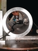
The deep-hole drilling (DHD) residual stress measurement technique is one of only a few techniques that can measure residual stresses at great depths (up to 750mm) within metallic and non-metallic components.
Data from DHD can be used to validate stress models, which can then be used as the initial state for simulations of crack propagation. These are used to define inspection frequencies and regimes for the continued safe operation of nuclear power plants.
DHD
The technique is a semi-invasive, mechanical strain relief technique (that is, the strain of the component is measured during stress relief from the removal of a small amount of material). The procedure used can be divided into four basic stages.
The diameter Ø0 of the reference hole measured in stage 2 is the diameter when residual stresses are present. During stage 3 the residual stresses are relieved, hence the diameter Ø of the reference hole measured in stage 4 is the diameter when residual stresses are not present. The difference between the measured diameters in stages 2 and 4 enable the original residual stresses to be calculated. The mathematical analyses used for the calculations originate from the theory of elasticity on the behaviour of a plate with a hole subjected to a uniform stress field.
A development of the technique, referred to as ‘incremental’ deep-hole drilling, increases the accuracy of the technique, particularly when measuring components with high levels of residual stress. If the stresses in the component are not high, the component will basically return to its un-stressed condition as the stresses are released, like an elastic band. However, if the residual stresses are extremely high, releasing them may induce a plastic flow in the metal, preventing a return to its un-stressed condition. It would therefore not be possible to accurately determine the original residual stress field, nor correctly model crack propagation. The incremental deep-hole drilling process releases the residual stress in incremental steps, rather than all at once. Although this does not prevent plastic deformation occurring, it is still possible to accurately determine the initial residual stress condition with this method.
VEQTER is now carrying out incremental deep-hole drilling as standard because the welds or regions of concern tend to be where there are very high stress levels. The incremental method was developed in 2008-09 at the University of Bristol, UK.
No single measuring technique is the best for all stress conditions or all parts of a component. If possible, several measurement techniques will be used to measure the residual stresses in a component. This also provides a level of validation and cross-checking between the different techniques used.
Research experience
VEQTER participated in two major programmes investigating component integrity in the wake of various corrosion problems, one in Japan and the other in the USA. A national programme entitled ‘Integrity Assessment of Flawed Components with Structural Discontinuity’, 2001-7, was organized by the Japan Nuclear Energy Safety Organisation. Several full-scale mock-ups of plant were built for this programme, with VEQTER and other organizations carrying out various measurement techniques. As well as carrying out some of the work at its laboratory in the UK, VEQTER shipped its test equipment to Japan to undertake on-site measurements on full-scale mock-ups. The results were pulled together to get best-case residual stress profiles through the components as well as to validate FE models [1, 2].
The US investigation, ‘Joint NRC/EPRI Weld Residual Stress Validation Program’, 2009-2011, did many of the same things as the Japanese programme. Mock-ups were constructed and round-robin exercises carried out using different techniques to measure and assess the residual stresses in these manufactured components and also to validate FE models. Among other results, this work led to the development of best practice guidelines for carrying out FE analyses [3, 4].
In both these programmes, deep-hole drilling was the main technique used to carry out measurements through the full thickness of the components.
VEQTER is also involved in assessing new fabrication methods and welding techniques as well as FE validation and safety case work for vendors such as Rolls-Royce in the UK and AREVA in France.
Recently VEQTER has also done work for Westinghouse and British Energy (now part of EDF Energy) for Sizewell B, Britain’s only operating PWR, on a potential cracking problem. The utility carried out residual stress measurements on mock-ups of components with the concerned welds and mitigating weld overlays in order to again validate FE analyses. The work is being used to prepare a safety case to demonstrate to the regulator that the stresses are known and can be managed using the weld overlay mitigation process [5].
Another project for EDF Energy concerns the integrity of the graphite moderator bricks within the utility’s advanced gas-cooled reactors (AGRs) which it hopes to continue to operate beyond the current licenses. The dimensions, and physical and material properties of the graphite moderator change due to the reactor environment, which generates stresses that can cause distortions and cracking. EDF Energy is predicting a mode change in the type of brick defects (from bore cracking to keyway root-initiated cracking), and therefore it is important to understand the measured stress state of the bricks. The build-up of stresses must be measured to determine if cracking might occur. VEQTER is developing a new deep-hole drilling machine that can work in high-radiation environments and can access the blocks using the current AGR inspection tools. EDF Energy hopes to be able to demonstrate that the stresses are lower than now estimated, and that the reactor will be safe for continued operation.
One project that was shelved by a Japanese company following the March 2011 earthquake and tsunami was to further develop the deep-hole drilling equipment so it could be used in irradiated areas rather than on mock-ups. The project was to develop an automatic remotely-controlled machine with a 50-metre umbilical to carry out the measurement work in the radiation zone. This required that the tooling and fixture change-over would be completely automated.
| Deep-hole drilling in a nutshell |
| Benefits of the DHD technique: Residual stresses can be measured at depths up to 750 mm Laboratory or 'on-site' measurements Through-thickness bi-axial residual stress distribution measured, including gradients High magnitude stresses can be measured (that is, it can take account of plasticity) Applicable to a wide range of materials, both metallic and non-metallic Applicable to both simple and complex component shapes Nominal accuracy: 10 MPa aluminium; 30 MPa steel; 15 MPa titanium Indifferent to surface finish of component Indifferent to grain structure/texture of component material Semi-invasive: enables repeated residual stress measurements at many different stages in component life Extracted cylinder of material provides stress-free sample for further material tests and validations Fast process in relation to quantity of stress information produced. Limitations of the DHD technique: Not applicable through components of less than 6 mm thickness Semi-invasive: the resultant hole might need to be re-filled or a mock-up be provided. |
Dr Ed Kingston, Managing Director, VEQTER Ltd, University Gate East, Park Row, Bristol, BS1 5UB.
References
1. Kazuo Ogawa, Ed Kingston and David Smith, "Measurement of residual stresses in full-scale welded components,’ SMiRT 19 conference, 12 " 17 August 2007, Toronto, Canada, Paper no. D04/4.
2. Kazuo Ogawa, Laurence O Chidwick et al. "Measurement of residual stresses in dissimilar metal joint of a safe-end nozzle component," Proceedings of PVP2009, 2009 ASME Pressure Vessels and Piping conference, July 26-30, 2009, Prague, Czech Republic, paper no 77830.
3. D.M. Goudar, E.J. Kingston et al. "Measurement of residual stresses in dissimilar metal welds using the deep hole drilling technique," Transactions, SMiRT 21, 6-11 November 2011, New Delhi, India, Div-II: Paper no. 159.
4. Matthew Kerr, Howard Rathbun et al, "NRC/EPRI weld residual stress finite element analysis validation," 2011 ASME PVP Conference, July 17-21, 2011, Baltimore, Maryland, Special Meeting
5. Stephen Marlette, Paula Freyer et al, "Simulation and measurement of through-wall residual stresses in a structural weld overlaid pressurizer nozzle," Journal of Pressure Vessel Technology [in press].