Calculating LOCA system effects
-
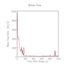
Figure 8: Break flow for 12-inch IBLOCA -
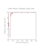
Figure 15: Lower plenum level for DEGCL -
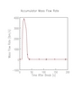
Figure 13: Accumulator flow in DEGCL -
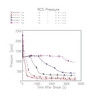
Figure 1: RCS pressure for SBLOCA by break size -
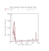
Figure 10: Safety injection for 10-inch IBLOCA -
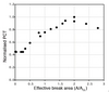
Figure 17: Peak cladding temperature against effective break area -
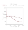
Figure 2: RCS pressure (1) and SG secondary side pressure (2) for three-inch... -
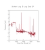
Figure 4c: Loop seal clearance prediction (differential pressure) -
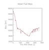
Figure 5: RCS fluid inventory for three-inch SBLOCA -
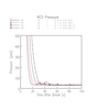
Figure 11: RCS pressure for LBLOCA by effective break flow area/type -
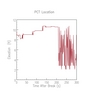
Figure 16: Peak cladding temperature location for DEGCL -
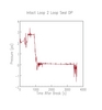
Figure 4b: Loop seal clearance prediction (differential pressure) -
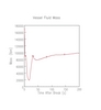
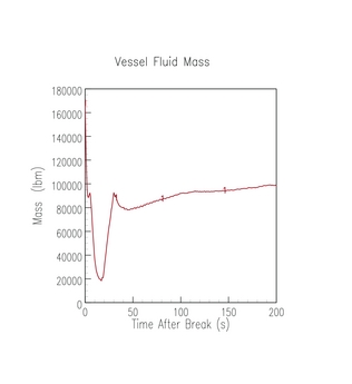
Figure 14: RCS fluid inventory in DEGCL -
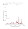
Figure 6: Safety injection for three-inch SBLOCA -
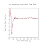
Figure 12: Vapour mass flow rate in core for DEGCL -
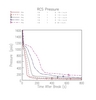
Figure 7: RCS pressure for IBLOCA by break size -
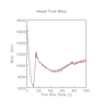
Figure 9: RCS fluid inventory for 12-inch IBLOCA -
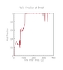
Figure 3: Break void fraction for three-inch SBLOCA -
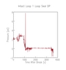
Figure 4a: Loop seal clearance prediction (differential pressure)

