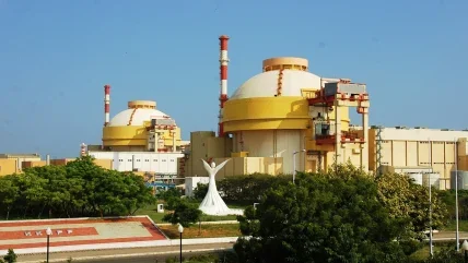
Kudankulam nuclear power plant, a 1000 MWe VVER V-392 due for startup in 2011, is located on India’s southern tip, in the Gulf of Mannar Biosphere Reserve. Since 1986 there has been a national park on the territory of the Mannar Bay.
The seawater is rich in living organisms and their waste products; their ingress into the nuclear power plant cooling system could not only damage it, but a high biota kill rate could harm marine ecosystems. Therefore, plant designers had to solve two problems: to minimise the power station’s ecological effect, and to protect the power station from the environment, in particular marine biota, sediment and adverse seawater chemistry.
Russia’s Hydroproject Institute has designed the service water intake for the Kudankulam 1&2 secondary side once-through cooling system, a large complex of interconnected structures providing cooling water from the ocean, its treatment and supply to NPP structures, and discharge to Mannar Bay. The cooling water flow volume amounts to 80.8m3/second per unit, and it will amount to 98.8 m3/s considering the fish protection system, according to Ruslan Shakirov, chief design engineer of the Kudankulam NPP service water supply system. In addition, the system has been designed to raise the temperature of the seawater at the discharge point by not more than 7°C. The customer, Nuclear Power Corporation of India, determined the level based on local seawater chemistry and other site conditions. To meet these requirements, Hydroproject has designed a unique water intake structure.
The main civil structure is a square enclosed dyke set 200 m offshore. Seawater at 31°C flows into it from a reinforced concrete intake pipe constructed 1200 m away from shore on the sea bed. The position of the dyke and its streamlined walls protects it from sediment blowing offshore into shallow water during windy weather. The near edge of the dyke forms an artificial canal, bounded on the other side by the seashore, which is spanned by a road bridge.
The Mannar Bay’s fertile seawater hosts a great range of organisms and biomass; at peak times of year they could amount to nearly 1.5 ton per 100 m3, almost double the maximum rate of traditional filtration systems. Ingress of such a large amount of biomass would inevitably result in power station stoppages, and serious consequences for the station’s electrical output.
Water intake structures minimise the amount of biomass entering the system. First, the position of the intake pipe at the sea bottom minimises uptake of biomass floating on the water surface (and also maximises uptake of the coolest seawater, which sinks to the bottom). Second, the edges of the dyke are made up with precast concrete tetrapod structures that create an artificial reef, diverting fish from the water intake zone (large fish can swim against the current generated in the intake structure). Third, the water that enters the dyke is filtered through a trash rack filter with cells 80 mm wide and 7 m high.
Those organisms that make it through the first rack then move through a fish protection system. This is designed for drifting organisms (12-60 mm in size) that are unable to cope with the current flow. A compressor situated in a service building on the near side of the dyke pumps air to a grid of holes on the bottom of the dyke. The air comes out as bubbles, which lift floating biomass as they rise to the surface. They are directed back into the sea (into the channel between dyke and seashore) through a fish tailrace system measuring 2.5 m across at minimum. A water ejector in the tailrace system increases water velocity. The ejector pump station is also located in the service building.
Meanwhile, the lower layer of water heads toward a supply pipeline. At this point, the bottom of the dyke incorporates chute structures that create underwater rapids, tending to slow down the flow of the lower layers of water. It is slower-moving water that enters a second intake pipe, again mounted at the bottom of the dyke.
The pipes cross underneath the channel to a forebay, where it is filtered again using a traditional water filter with rotating, self-cleaning grids. To save energy, the machine stops working if the incoming water is clean. The system is designed to have a kill rate of only 20% (by comparison, Russian regulations are 30%). This water is then used by a 22 MW pumping station for secondary side once-through cooling.
The main reinforced concrete structural elements of the service water supply system are submerged in seawater, which has a slightly higher concentration of salt than typical. Salt tends to erode traditional waterproofing treatments for concrete and steelwork. Hydroproject used titanium and steel with special polymer coatings. Two more water intakes are planned, one for the planned units 3-6, and one for the planned units 7-8.
For future intake units at Kudankulam, Hydroproject expects to use a slightly different design, and also new materials for reinforced concrete corrosion protection. It won the contract for a feasibility study of intake structures for units 3&4. A purchase decision is expected by the end of the year.
The structures used in this application can in principle be used in any hydropower project to reduce water contamination and protect biota.
This article was originally published in the September 2011 issue of Nuclear Engineering International (p55-56)
Author Info:
Kirill Mirjushenko, strategy director, Ruslan Shakirov, project engineer, Alexander Invanov, water management and ecology advanced engineer, Vera Vishnevskaya, specialist, Institute Hydroproject, 2, Volokolamskoye shosse Moscow, 125993, Russia
Related ArticlesRussia and India agree construction roadmap China and India-now even more important to nuclear?


