Power plant design
The best of both
9 April 2009Over the last forty years, both PWRs and BWRs have proved they can operate safely and successfully. So why not combine their best features in a new reactor design, while at the same time avoiding some of the components that have proved problematic? By Frigyes Reisch
Now Generation III+ reactors are becoming a reality, with construction of the EPR well underway in Europe and plans to start building AP1000 units at Samen in China within the next month, the time has come to look ahead to improved nuclear power plant designs. The High Pressure Boiling Water Reactor (HP-BWR) is one possibility. Based on operating experience with conventional BWRs and PWRs, the HP-BWR concept combines the advantages of each traditional design, but leaves out the troublesome components to give a safe, environmentally friendly and economical plant.
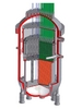
Common sense, public confidence and economic considerations demand that the new HP-BWR design should not be a big leap from presently operating reactors; however it should be a significant improvement on them. Therefore the parts of the older designs that have caused trouble in the past, for example PWR steam generators and BWR perforated reactor vessel bottoms, have been removed. Instead the HP-BWR design relies on proven components such as the pressure vessel and the control rod drive systems from the PWR, and the core internals, circulation pumps and steam-moisture separators from the BWR. The HP-BWR is shown in below.

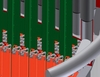
Unlike a conventional BWR, the control rods enter from the top and are gravity operated, as this system has served well in PWRs. However in the HP-BWR the shape is cruciform, as it is in BWRs. This assures a large clearance between the BWR type fuel assemblies. The bottom of the HP-BWR reactor vessel is also free of the numerous control rod penetrations, found in conventional BWRs.
All the pipe connections to the HP-BWR reactor vessel are well above the top of the reactor core. This means that a major pipe break will not empty the reactor vessel and therefore core spray is not needed.
Internal circulation pumps are used in the HP-BWR to assure hydrodynamic stability. The orifices at the fuel channel inlets are chosen so that the one phase pressure drop will dominate over the two-phase pressure drop, avoiding hydrodynamic oscillations. By utilising natural circulation one could even omit the recirculation pumps, but the margin against hydrodynamic oscillations would be reduced.
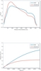
The conventional BWR and HP-BWR designs have similar power distributions (see Figure below), however this is something that can be changed with different fuel designs.

Compared with the traditional BWR, the HP-BWR has further advantages, namely improved thermal efficiency due to the higher temperature and further improved inherent stability due to the increased negative power reactivity coefficient (see Figure above).
The improved thermal efficiency is achieved by feeding the turbine with 618K (15.5MPa) steam, instead of steam at 559K (7MPa) as in a conventional BWR. The Carnot cycle theoretical efficiency (THot - TCold )/THot is ~46% for a BWR and ~51% for a HP-BWR at TCold=300K. That is, the theoretical efficiency increases by a factor of 1.109. Assuming the same improvement ratio, HP-BWR efficiency would increase to ~37 % compared with ~33% for the conventional BWR. This demonstrates the advantage of the HP-BWR, which utilises the fuel more efficiently and releases less warm cooling water to the environment per produced kWh.
On the other hand, the HP-BWR retains the direct cycle employed in conventional BWRs, contributing to simplicity and reduced cost, and avoids complex and problematic steam generators. Another advantage of the HP-BWR is that it avoids the BWR reactor pressure vessel bottom, which is rather complicated from a manufacturing point of view. Leakages have also occurred in several BWR pressure vessel bottoms. Because there is deposition of a lot of corrosion products inspection and repair is very difficult. The main steam separators are inside the pressure vessel and secondary separators and dryers can be installed outside the reactor vessel, inside or outside the containment. The simple dry containment allows for easy entrance, inspections and also minor repair during operation.
Author Info:
Frigyes Reisch, Nuclear Power Safety, KTH, Royal Institute of Technology Alba Nova University Centre, Roslagstullsbacken 21, S-10691 Stockholm, Sweden. The author would like to thank Hernan Tinoco and Karl–Axel Bartholf of the Forsmark nuclear power plant for the CAD designs and Joanna Peltinen of KTH for the RELAP and PARC calculations.
Related ArticlesTransforming Forsmark