Slowing down expectations
29 March 2011Since the 1970s, major decisions on development of sustainable closed fuel cycles have been based on the assumptions that uranium resources are limited and that consequently what is required is a fast reactor with as high a conversion ratio as feasible (which turns out to be 1.2 to 1.3). These assumptions drove fuel cycle decisions. The 2010 MIT study ‘The Future of the Nuclear Fuel Cycle’ concludes that both assumptions are incorrect—uranium resources are large and a conversion ratio of unity is preferred.
The evolution of the nuclear energy system will depend on future demand for nuclear energy, and the reactor and fuel cycle technologies deployed to meet this demand. There are several options for the nuclear fuel cycle. The simplest cycle, which is applied today in the US, relies only on mined uranium as fuel, while advanced cycles rely at least partially on fissile material extracted from the discharged fuel of other reactors. Therefore, fuel cycle options imply different levels of demand for the uranium resource and for industrial infrastructure for fuel recycling, and result in different amounts of spent fuel and of materials to be disposed of as waste.
The base case assumes that the nuclear energy capacity grows to 120 MWe in 2020, due in part to power uprates of existing reactors, followed by an annual nuclear energy growth rate of 2.5% from 2020 until the end of this century. Such a growth rate will be higher than the growth rate of nuclear energy production in the last two decades, and will result in an increase in the portion of electricity supplied by nuclear plants given the expected annual growth in electricity of 1 to 1.5%. If annual electricity growth between now and 2050 is at 1.5%, the nuclear share will be about 28% in that year. Thus it reflects an assumption that nuclear energy will be relied upon for part of the carbon emission reduction while meeting future demand for energy. A case of lower growth rate of 1% per year and a case of higher growth rate of 4% after 2020 are also examined.
The fuel cycle options considered include the once-through cycle (OTC) using light water reactors, practiced today in the US, but the basic conclusions are applicable anywhere. Three advanced fuel cycle schemes are also explored in this study (1) Pu recycling in the form of mixed oxides in LWRs (‘MOX scheme’), (2) transuranic (TRU) multi-recycling in fast reactors (FR) designated as advanced burner reactors (ABR) of various fissile conversion ratios from 0 to 1, and (3) TRU recycling in a fast reactor designated as a breeder (FBR), of which the fissile conversion ratio is 1.23. The schemes involving recycling of TRU in fast reactors have also assumed uranium recycling.
The analysis is conducted via the MIT-developed fuel cycle system simulation code CAFCA [1]. The code tracks the infrastructure involved in the nuclear energy supply, the basic material flows in and out of facilities, the inventories in storage and awaiting waste disposal and the economics of the entire enterprise. It applies several simplifying assumptions, but has been found sufficiently accurate for the level of detail required for a system study [2]. All the advanced fuel cycles considered here are for a one-step switch from the once-through cycle to an advanced fuel cycle.
Key characteristics
The once-through scheme (denoted OTC) is the fuel cycle currently practiced in the U.S. and is considered as the reference case. In this scheme, UO2 assemblies are loaded in the thermal spectrum light water cooled reactors, irradiated for a period of a few years, discharged and left in ‘cooling storage’ (typically in reactor pools) for a few years (a ‘minimum cooling time’). Finally, the spent fuel is sent either to interim storage or to a repository.
For the sake of simplicity, we use a single model of a reference 1000 MWe LWR, and assume a unique set of parameters for the fuel cycle. Data about the fuel requirements are taken from [3]. In reality, there are many sizes of LWRs, and their fuel cycles also differ according to their fuel management. Table 1 summarizes the characteristics of interest for the reference LWR (scaled to a 1000 MWe unit) as well as all other reactors considered in this study.
A ‘fast reactor’ is a nuclear reactor in which most fissions occur due to neutrons with energies above 1 keV, while thermal reactors fissions occur mostly by neutrons with energies under 1 eV. At the higher energies, fission cross-sections are smaller, which leads to the need for higher enrichment and higher neutron fluxes in fast reactors. On the other hand, the probability of fission relative to sterile neutron capture is much higher in a fast spectrum for most of the U and TRU isotopes. Hence, burning of plutonium in fast reactors generates fewer higher-mass transuranic isotopes than in thermal reactors. In other words, fast reactors can achieve a relatively more uniform destruction of the TRU isotopes.
When fast reactors are designed to be net consumers of TRUs, they are called ‘burners’ and are characterized by their fissile conversion ratios (CR). The conversion ratio is defined as the ratio of the rate of production of fissile materials to the rate of destruction of the existing fissile materials, approximated by ‘the ratio of the macroscopic cross section of U-238 capture to that of TRU fission’ [4]. They may range from CR=0.0 (fertile-free) to CR=1.0 (break-even, or self-sustaining). When fast reactors are designed as net generators of TRU they are called breeders, with a CR >1.0.
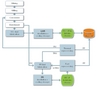
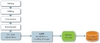
The fast burner fuel cycle requires reprocessing of the UO2 fuel discharged from LWRs, after an appropriate cooling time. Transuranics are separated from the fission products in thermal reprocessing plants (uranium is also recovered in the process). These transuranics are mixed with depleted or natural uranium to fabricate fast reactor fuel pins. Fuel assemblies are loaded into fast reactors, irradiated, discharged and decayed over a minimum cooling time. They are then reprocessed in fast reprocessing plants in order to be recycled back into a fast burner. The mixture of uranium and transuranics is separated from fission products (which are sent to disposal) and used to fabricate fresh pins for the fast reactor. Thus, feed materials for fast reactor fuel come from two sources: external supply (TRU separated from LWR spent UO2 fuel) and self-recycling (U-TRU mix separated from spent FR fuel). As the scheme allows for multi-recycling, it is also known as a closed fuel cycle: only unusable fission products are eventually sent to disposal. Figure 2 shows a representation of the fast reactor fuel cycle, which also applies to the fast breeder scheme.
Unlike a burner fast reactor design, in which limited fertile material is included, a fast breeder reactor requires fertile materials such as U-238, often in blankets surrounding the core, to generate more fuel than it consumes. The blankets are placed in radial and axial positions adjacent to the core. This results in fissile conversion ratios higher than 1.0, therefore often called breeding ratios. However, to compensate for the larger inventory of fertile material in the core and neutron absorption in the blanket, the core may require a higher inventory of fissile isotopes. The core is refueled with transuranics from reprocessing the core and blanket materials. Hence, the TRU mass in the core of a breeder is typically larger than that of a burner core of similar characteristics. However, the fissile material throughput per GWe should be slightly smaller, due to increased buildup of fissile material in the blanket. The past designs of breeder reactors have had a range of fuel inventories per GWe, even when the same fuel material was used [5].
Having made the distinction of the conversion ratio, the fast breeder fuel cycle scheme is otherwise exactly the same as the fast burner scheme. Differences are quantitative: while a burner (especially of low conversion ratio) will continuously need an external source of TRU (typically from spent LWR fuel) to augment the supply from self-recycling, a fast breeder actually becomes a net source of fissionable materials, as TRU production exceeds its own needs.
We use as a reference breeder reactor for this study the Advanced Liquid Metal-cooled nuclear Reactor (ALMR), which has a breeding ratio of 1.23 [6&7]. The ALMR was designed by GE to a greater depth than other metal-cooled reactors. Given that the burner reactors used as reference here are metal- fuelled, it is appropriate to use a metal fuel reactor as the reference breeder. Table 1 summarizes the main characteristics of the reactor (scaled up to 1000 MWe from a 319 MWe unit). It is realized that simple size-scaling of the fuel needs would only be an approximation, given the change in surface-to-volume ratio and implications for neutron leakage from the core. However, such approximations introduce secondary effects that can be tolerated in exploratory system studies.
Models and assumptions
The CAFCA code is a materials balance code that tracks the nuclear fuel materials through the various facilities needed to extract, process and burn the fuel in the reactors, then account for the discharged fuel in cooling storage, or longer-term interim storage, before it is either sent for disposal in a repository or reprocessing to provide some of the needed fuel for reactors. The demand for nuclear energy can be specified in time, and the available nuclear technology can also be specified. In our analysis the LWR is assumed to be available at all times, but reactors that depend on recycling technologies are assumed to become available only at a future time. Here we briefly describe the key assumptions of the analysis. More details are available in [8].
All reactors are assumed to have a lifetime of 60 years. While the initial licence of existing LWRs in the US was issued for 40 years, about 60% of these plants have already received 20-year licence extension.
It is assumed that the remaining LWRs will also be able to get such a licence extension. All new LWRs and fast reactors are assumed to have 60 year operating licence. However, fuel reprocessing plants are assumed to have a lifetime of only 40 years, after which they are retired to allow for new technology to be built.
The dynamic simulation starts with an initial installed capacity of 100 GWe at the start of 2008, and spent UO2 fuel inventory of 56,800 tHM (tons of heavy metal). The minimum cooling time is five years for all types of discharged fuel.
In the MOX option, the first thermal reprocessing plant starts operation in 2025, and the separated plutonium is immediately used to make MOX fuel. In the options involving fast reactors, the first thermal reprocessing plant starts in 2035, five years prior to the introduction of the fast reactors in 2040.
As for the size of the thermal reprocessing plants, a single 1000 tHM/year unit is assumed in all scenarios; this is 25% larger than the most recent plant built in the world (the Rokkasho plant of Japan) but is smaller than the 1700 tHM/yr capacity of the La Hague plant that was built in pieces over several decades. In addition, to make choices that trade off between economies of scale and modularity, we assume different sizes of fast reprocessing units, as suitable for the demand, with the values shown in Table 2.
Another parameter is the industrial capacity to build these processing facilities. The thermal reprocessing plants are assumed to take four years to build and licence after the need is identified, which means that only one plant can start commercial operation every four years (including construction time). This industrial capacity is doubled after 2050. As for the fast reprocessing plants, initially (they are available after the year 2040) the industrial capacity is constrained to two years/plant, but is doubled after 2065. At that point, it is assumed that the licensing of such facilities become faster than it was when they were first built. Finally, a minimum loading factor of 80% is generally imposed for the reprocessing plants over their lifetime, meaning that they are only built if a minimum of 80% of their capacity is needed over their lifetime of 40 years. However, some exceptions have been allowed.
Impact of fuel cycle options on infrastructure
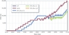
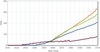
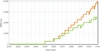
Figure 3 shows the total LWR-UO2 installed capacity in the various fuel cycle schemes for the base case of annual growth of 2.5% per year, while Figure 4 shows, for the same schemes, the installed capacity of the advanced reactors involving recycling of discharged fuel from LWRs and/or fast reactors. Recall that the capacity factor of the LWR and that of the FRs differ (90% vs. 85%). Therefore, the total installed capacity may vary from one scheme to another, but the total energy produced per year does not.
As expected, the breeder installed capacity will over time become greater than that of the other FR options, and those in turn will reach a larger capacity than LWRs-MOX. Table 3 shows the installed capacity of each technology for the once-through fuel cycle and the four main scenarios in 2050 and 2100 for the three cases of growth rates. It is clear that only in the slow growth scenario would the capacity of fast reactors dominate the nuclear energy supply system by the end of century. In the higher growth scenarios, the LWR will continue to play a major role, providing more than 50% of the nuclear capacity even at the end of the century. This is a result of the traditional assumption that to start up FRs only TRU from LWR spent fuel and FR spent fuel can be used. For a high growth rate, it takes many more LWRs to produce the plutonium needed for startup of the fast reactors.
However, it is noticeable that in the base growth case and high growth case, the penetration of a breeder fast reactor at 2100 is close to that of the self-sustaining fast reactor (391 vs. 345), and both have a significantly higher installed capacity than that of the fast burner (259). At first glance this appears strange, since the added fissile production in the case of the breeder should enable added FR capacity. However, the fact that the initial core of the breeder reactor requires more fissile material explains the similarity of the two figures. The burner and self- sustaining fast reactors minimize the presence of excess fertile material (blankets), whereas the higher breeding ratio reactor needs such blankets. Thus, it needs more fissile loading to compensate for neutron absorption in the blanket.
Reprocessing plants
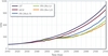
Figure 5 shows the development of the thermal reprocessing capacities in the various fuel cycle schemes for the 2.5% growth case. Recall that the unit capacity is 1000 tHM/year and that thermal reprocessing is introduced in 2025 in the MOX scenario versus 2035 in the FR scenarios. The need for thermal recycling capacity is nearly the same for all schemes until 2070, with somewhat larger capacity needed for the case of a fast burner. However, after 2070, the need for thermal recycling capacity in the case of MOX goes well above the FR cases, due to the exhaustion of the spent fuel in interim storage, and the presence of fissile fuel from reprocessing fast reactor fuel in the FR cases.
As long as no reprocessing is introduced, spent UO2 fuel discharged from LWRs accumulates in interim storage. A few years after the introduction of the first thermal reprocessing plant, this stockpile reaches a peak, as the reprocessing rate overtakes the inflow rate. In the MOX scenario, the stock of spent UO2 fuel peaks at 91,000 tHM in 2033 (8 years after introduction of the first reprocessing plant). In the FR scenarios, the peak occurs at 127,000 tHM in 2050 (15 years after the introduction of the first plant).
Figure 6 shows the development of fast reprocessing capacity in two cases: The self- sustaining FR with CR=1 and the FR breeder with CR=1.23. Recall that the unit capacity of a reprocessing facility is 500 tHM/year both of these cases. Also, in both scenarios, the first reprocessing plant starts in 2051, 10 years after the construction of the first FR. By that time enough spent fuel had accumulated to enable the plant to operate above the minimum allowed 80% capacity over its lifetime. The reprocessing capacity needed is much higher in the breeder case than in the self-sustaining case (8,000 tHM/year vs. 5,000 tHM/year in 2110) for two reasons: (1) there are more installed fast reactors (391 vs 345 GWe in 2100) and (2) more significantly, the annual refueling rate of a breeder is larger than that of the self sustaining case (14.8 vs. 11.2 tHM/year/GWe). However, the TRU content in the discharged fuel is about the same (1.507 vs. 1.571 tHM of TRU/year from a 1 GWe breeder versus an FR with unity conversion ratio).
Impact on natural uranium requirements and cost
The introduction of advanced technologies automatically reduces the need for mined natural uranium. The recycling of Pu or TRU from spent fuel as well as the recovered uranium from thermal reprocessing plants, instead of natural uranium, leads to these savings. Table 4 shows the cumulative natural uranium utilization for various fuel cycle schemes by the years 2050 and 2100 for the three reference growth rate scenarios. Table 5 gives the rate at which mined uranium will be needed in 2050 and 2100 for these cycle options, for the growth rate case of 2.5%.
The 2100 results are the better indicator of the long-term impact of various fuel cycles, as the system becomes nearer to equilibrium, whereas at 2050 the spent fuel legacy is not depleted yet, providing extra amounts of fissile plutonium and recovered uranium, and the fast reactors are just starting to be deployed.
As seen in Table 4, in terms of cumulative uranium savings, for all growth rates, the breeder scenario has nearly the same total U demand as the fast reactors with unity conversion ratio. This is somewhat unexpected given that breeder reactors produce more fissile material than they consume, whereas the CR=1 case reactors produce an amount only equal to what they consume. Upon reflection, it is a logical outcome given that the startup of the breeder reactor requires more TRU than that of the CR=1 case. The net effect is that the total savings of uranium is about equal.
However, the rate of uranium use is diverging, as can be seen in Table 5. For the base case of 2.5% annual growth, the breeder fuel cycle yields the best results in the year 2100 in terms of natural uranium savings compared to the once-through LWR cycle, reducing its consumption in that year by almost half (46.6%). The burner strategy is less efficient (32.9%) while the MOX strategy only yields very modest results (16.0%, of which half is due to the utilization of recovered uranium). When only TRU is recycled, the reduction in the uranium needed is less than when the discharged uranium is recycled as well.
Startup of fast reactors with enriched uranium
One option to avoid the coupling of fast reactor startup with reprocessing of LWR spent fuel is to start fast reactors with a core of enriched uranium rather than TRU. As can be seen in the preceding results of the nuclear fuel cycle, the availability of TRU from LWRs for the initial fast reactor core places an upper limit on the deployment rate of fast reactors. Alternatively, starting fast reactors with enriched uranium, and multi-recycling of the resulting TRU, may allow building a larger number of fast reactors, which in turn would save uranium resources. If only fast reactor TRU was recycled, this strategy would obviate the need for facilities to recycle LWR TRU. Many experimental fast reactors were started using medium- and high-enriched uranium, higher than the current limit on commercial reactor enrichment of 20%—the dividing enrichment between weapons usable and non-usable enriched uranium.
Historically it has been assumed that medium-enriched uranium or plutonium was required to start a fast reactor. Core simulations at MIT show suitable performance for a sodium-cooled fast reactor (SFR) fueled by enriched uranium below 20%, provided the desired conversion ratio stays about one (according to [9]). The reference uranium-initiated SFR design with CR=1.0 achieved a burnup somewhat below 100 MWd/kg using 19.5% enriched uranium oxide fuel with a magnesium oxide (MgO) reflector. The same burnup could be achieved using 14% enriched metal fuel and MgO reflector. After reaching the limiting burnup, the core would be discharged and its TRU content recycled to provide fuel for the next irradiation. In principle, the TRU would continue to be recycled and the fast reactor would operate in a self-sustaining fashion.*
(* The amount of TRU discharged after the initial core may not, in fact, contain sufficient reactivity to sustain the next fast reactor cycle. This has yet to be confirmed. If a reactivity gap exists, it might be filled to some extent by further dropping the initial uranium enrichment (which is potentially possible with more exotic fuels), thus increasing the breeding ratio of the initial core. Otherwise, other makeup fuels would need to be mixed in with the second-recycle core. The makeup fuels can be small amounts of low enriched uranium.)
The use of enriched uranium to start fast reactors with near unity conversion ratio provides a scheme to divorce the speed with which fast reactors can be deployed from the availability of TRU to fuel their initial cores. This facilitates a faster penetration of the nuclear energy system by fast reactors. The lower conversion ratio compared with breeders may also permit a greater range of FR technologies. In addition, such a route to fast reactor avoids the building of a large thermal fuel recycling capacity, which is the costly part of nuclear fuel recycling infrastructure. However, the spent fuel generated by LWRs has to be disposed of in a safe and secure manner, requiring a repository with sufficient capacity.
Author Info:
This article is an edited version of chapter 6 of The Future of the Nuclear Fuel Cycle, an MIT interdisciplinary study. For more information, see http://www.neimagazine.com/mit1. References have been omitted because of lack of space but are available on http://www.neimagazine.com/mitfu