Russia focus: power plant design
Passive safety in VVERs
26 August 2011Key safety system functions in the new Russian reactor design are performed by both traditional active systems and novel passive systems that do not require external power, a design that is currently unique among PWRs. In particular, the passive heat removal system and the passive filter system are discussed. By V.G. Asmolov
The combination of using active and passive systems to perform safety functions was adopted during development of an AES-92 reference design that served as a basis for Kudankulam NPP (India) project, and has been included in the AES-2006 and VVER-TOI NPP designs. The approach helps to practically exclude the possibility of a severe accident with core damage, which sets AES-92, AES-2006 and VVER-TOI apart from the other PWR plants developed outside Russia.
To provide one of the reactor design’s crucial safety functions—emergency heat removal from the core—the design incorporates active safety systems, including emergency and normal cooling systems for the primary circuit, emergency high-pressure make-up systems, emergency steam generator cooling systems, and support systems (intermediate circuit, service water, power supply). See also Figure 1.
To ensure emergency heat removal from the core by passive safety systems, the plant is provided with a passive heat removal system (PHRS) and a system of water tanks (‘hydraulic accumulators’) in a first and second stage (HA-1 and HA-2). If a loss of all AC power sources at the site causes an active safety system failure, and that failure is not accompanied by a loss of coolant from the reactor circulation circuit, operation of the passive heat removal system alone will be sufficient to cool the reactor. Owing to the use of air as an ultimate heat sink, the PHRS can perform its function for an unlimited period of time in these conditions.
To cope with leakage of primary coolant accompanied by failure of active safety systems, sufficient reactor cooling will be provided by water tanks of the first stage in operation to flood the reactor vessel. Operation of the second-stage tanks and of the PHRS is necessary for long-term heat removal from the core. In this case, the PHRS uses the steam generators (SG) to condense primary circuit steam from the reactor. Due to this, the steam generator condensate goes back to the primary circuit to complement water supplied by the second-stage tanks.
Considering the condensing ability of the steam generators, water inventory in the HA-2 tanks was chosen so that coolant inventory essential for reliable cooling of fuel can be maintained in the reactor vessel for 24-280 hours (depending on leak size). To make the reactor self-sufficient in case of any leakage, including a break in the main circulation pump, it is possible to use additionally the water from the spent fuel storage pool for at least 72 hrs (an extra inventory of about 800 m3).
In an initiating event involving loss of all AC power sources without the loss of primary coolant, PHRS operation is not limited in time and does not require any special accident management actions. However, the spent fuel storage pool located inside the containment causes pressurisation inside the containment due to the water boiling out in the pool. It takes about 10 days for the pool water to boil down to the top (‘head’) of the spent fuel assemblies, and for the pressure inside the containment to rise to the design level of 0.5 MPa (abs). After that, it will be necessary to take actions to add water to the pool. Up to 0.7 MPa, there is no need to take actions to limit containment pressurisation because the containment leaktightness will not be in jeopardy up to this level of pressure.
In case of an initiating event involving the loss of all AC sources and loss of coolant from the primary circuit, energy dissipation owing to PHRS operation maintains parameters of the steam-gas environment in the containment at a level below the design value of 0.5 MPa (abs), which guarantees fulfilment of the confinement functions of the containment. To prevent environmental release of radioactivity discharged into the inter-containment cavity through leaks in the primary containment shell, the inter-containment cavity is kept decompressed, and the medium is discharged into the atmosphere via the filters using a passive filtering system (PFS).
Passive system design
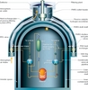
The key design characteristics of the passive safety systems are described below. A basic diagram and composition of passive safety systems in a VVER-TOI plant is given in Fig. 2.
The second stage water tanks (hydraulic accumulators) are intended to inject boric acid into the core for at least 24 hours in case of a maximum two-side loss of coolant in the primary circuit (stored concentration: 16g/kg). The system is actuated in the event of a loss of coolant in the primary circuit and pressure decrease in the reactor to ? =1.5 MPa.
In case of the loss of primary circuit leaktightness, the second stage water tanks are used to cool the core, together with water tanks of the first stage and PHRS.
For this, the second stage water tank system features the following:
• stepwise profiling of water flow injected into the core as water inventory decreases in tanks. Flow profiling corresponds to the decrease of residual heat
• total coolant inventory in water tanks amounts to 960 m3
• coolant inventory has been chosen so as to ensure reactor make-up with coolant during 24 hrs in case of the maximum loss of coolant in the main circulation pipeline.
The system consists of four water tank sets. Each set comprises two tanks with drain pipes providing profiling of coolant flow. Coolant flows to the reactor from HA-2 due to the hydrostatic pressure. On the side of the drain line, the second stage tanks (HA-2) are hooked to the pipelines connecting the first stage tanks (HA-1) to the reactor. The upper part of the HA-2 tanks is connected, via special check valves, to the cold legs of the main circulation pipelines, in the immediate vicinity of the SG headers. Special check valves are set to open in case of circuit pressure decrease to 1.5 MPa.
In abnormal conditions involving the coolant loss from the primary circuit, as the reactor pressure falls, first water tanks of the first stage start up (at ? < 5.9 MPa), and then second-stage tanks come into play (at ? < 1.5 MPa).
HA-2 injects solution in four stages of 40, 20, 13.2 and 7.1 kg/s flow, each of varying duration, over 24 hours. The flow characteristics have been confirmed in the experiments performed at integral test facilities ISB-VVER and PSB-VVER, as well as at a full-scale mock-up facility of HA-2, which simulated actual coolant flow from the system to the reactor.
PHRS
The passive heat removal system is designed to provide a long-term removal of residual heat from the reactor in case of a beyond-design-basis accident involving the loss of all AC power sources. In the event of a loss of coolant from primary circuit, the system provides removal of residual heat together with water tanks of the second stage.
The system consists of four independent trains; one per each steam generator. Each train comprises two heat exchangers/condensers, steam condensate pipelines with valves, air ducts with air shutters and a controller.
Steam comes to the PHRS heat exchanger from a pipeline of each SG. Steam is condensed in the heat exchangers by atmospheric air. The air is taken from atmosphere outside the containment building. Owing to natural draft, the air goes into a ring header running around containment building. After that, air goes to heat exchanger modules via individual air ducts. Air condenses steam in the heat exchanger modules and goes into the draft shafts, which end in a common header with a deflector.
While on standby, the heat exchangers of the system are warmed to the secondary circuit temperature, which rules out thermal cycling on PHRS initiation and provides the best dynamics for PHRS to pick up its rated capacity. Upstream and downstream of each PHRS heat exchanger module are closed gate valves that open on a loss-of-power signal. The valves serve to protect the equipment against an air shock wave and minimize heat losses at the unit while the system is on standby.
Between the gate valve and the heat exchanger module is a controller furnished with two drives, one active and one passive.
The passive drive is a bellows spring unit that actuates the opening or closing of shutters, depending on steam pressure variation in the steam generator. Controller shutters are normally open during on-load operation. The shutters start to close if the SG steam pressure falls below 5.8 MPa, helping to maintain steam pressure close to nominal values.
The passive PHRS shutter controller drive controls the process of heat removal from the reactor in case of beyond-design-basis accidents where there is loss of all AC sources at the site, but without primary circuit coolant leakage.
If the loss of AC power is accompanied by primary-circuit leakages, those leakages result in a steam pressure decrease in the SG, the PHRS system is transferred into reactor cooldown mode using the active drive (powered by batteries). Besides, the active drive allows operator, if necessary, to control the heat removal process with the PHRS. The capacity characteristics of one PHRS train with fully-open shutters is given in Table 2.
The capacity characteristics of the PHRS and the control characteristics of the passive drive have been validated in experiments performed at the PHRS test rig at OKB Gidropress, where the tests were run using a 1:2 heat exchanger/condenser (Gidropress design) and a full-scale drive (OKBM design).
Passive filtering system
An architecture of cross-connected passive systems is implemented in the VVER-TOI design. A logical continuation to incorporating the PHRS system in NPP design is the use of a passive filtering system (PFS) to filter leakages from the inner containment shell into the inter-containment cavity. To operate, PFS uses the thermal energy of air passing through PHRS heat exchangers/condensers. The PFS system uses the space between the outer and inner shells of the containment to collect inner shell leakages. The system comprises heat exchanging channels (item 13 in Fig. 2) and a filtering facility with a vent pipe (item 12). The heat exchanging channels (13) have inlet valves and are hooked to the inter-containment cavity at their inlet and to the filter at the outlet. The heat exchanging channels are located in the hot air ducts of the PHRS system (8); they warm up and dry the steam-gas leakages coming to the filter.
The passive filtering system operates in the following way. In normal operation, the inter-containment cavity is cooled by a regular ventilation system, while the valves connecting the inter-containment cavity to the heat exchanger channels (13) and the gate valves (14) are closed. There is a small flow of warm air in the draft shafts because of leakages in the air line, resulting from limited leaktightness of the PHRS gate valves. Passing through the PHRS heat exchangers, air warms up PFS components (13), and keeps the system continuously available for operation following PFS valve (14) opening.
In case of emergency leakages from the reactor, pressure inside the inner containment shell rises, and radioactive leakages from the inner shell appear in the inter-containment cavity, where the regular ventilation system, if operating, provides decompression and directs leakages to the filter.
If the regular ventilation system fails, the PFS would depressurize the inter-containment cavity.
Owing to the energy of the hot air passing in shafts (8) and washing the heat-exchanging channels (13), the condensed moisture present in leaked air is dried out, and the leaked air warms up. The warming of the air inside components (13) creates gravitational convection, which acts to decompress the inter-containment cavity relative to the pressure in the surrounding air environment.
Since the PFS system also terminates in a filter, decompression of inter-containment cavity precludes uncontrolled non-filtered radionuclide release in the environment. Using the thermal energy of the PHRS air, the passive filtering system provides filtered leakage discharge into the atmosphere. The flow characteristics of the PFS are determined based on the decompression required in the inter-containment cavity.
Calculations and experiments were carried out to validate the thermal capacity and hydraulic parameters of PFS. The design solutions adopted for PFS ensure that the leaked air will warm up, dry out, and decompress the inter-containment cavity. Sorption filtering materials have been developed and tested to ensure appropriate filtering.
The PFS filtering facility has a modular configuration. Two reference modules were manufactured and tested in a wind (aerodynamic) system in the IPPE (Obninsk) hot cell. The tests have proved the designed filtering factors of the PFS.
Passive hydrogen recombiners
The VVER-TOI design uses RVK-type passive catalytic recombiners of hydrogen (item 15 in Fig. 2) whose efficient flame-free operation has been substantiated for bulk hydrogen concentrations ranging from 0.45% to 16%. A total of 160 passive catalytic burners are installed across the containment. Owing to this, average bulk concentration of hydrogen in the containment should not exceed 6%, protecting the plant from hydrogen explosions in design-basis and beyond-design-basis accidents.
Conclusion
Performance characteristics of the passive safety systems used in VVER-TOI design were chosen relying on the computational simulation of various design-basis and beyond-design-basis accidents, and were validated by simulating the systems performance on large-scale test rigs. OKB Gidropress, the Kurchatov Institute national research centre, IPPE and other organisations rendered great assistance to Atomenergoproekt by providing valuable inputs into the computational and experimental studies undertaken to validate the design solutions.
Large-scale experimental facilities were set up to perform experimental validation of the passive safety systems.
The passive technologies discussed above are specific to AES-92, AES-2006 and VVER-TOI designs developed by Atomenergoproekt. They are not present in any other designs of operating NPPs or plants currently under construction. The design characteristics of these passive safety systems, confirmed in the tests performed at large-scale experimental facilities, prevent – with high degree of certainty – fuel damage above the design limits for at least 72 hours in case of a beyond-design-basis accident involving loss of coolant from the primary circuit, and during a greater period (up to 10 days) in the event of the loss of all AC sources that is not accompanied by coolant leakage. The engineering solutions used in the passive safety systems design allow further upgrading to prolong plant self-sufficiency in any initiating events, including those which are very unlikely.
FilesFig. 1: Diversity in safety function implementation in a VVER-TOI plant. Passive systems shown in red type. Fig. 2: Passive technologies embodied in Novovovoronezh II reactor containmentTablesTable 1: One PHRS train capacity (in MW) depending on atmospheric air temperature and pressure in steam generator