Power plant design | Core
Four-year SMR fuel cycle
1 November 2012Although the B&W mPower™ integral pressurised water reactor uses 69 standard (but reduced-height) 17x17 PWR fuel assemblies, the vendor is offering a core loading and cycle management plan for four years of continuous power operations without refuelling and without the hurdles of chemical shim. By Madalina Aimee Erighin
Since 2008, The Babcock & Wilcox Company (B&W) has been engaged in the development of the B&W mPower reactor, a small, rail-shippable integral pressurized water reactor (iPWR) with a once-through steam generator and a nominal electric power output of 180 MWe, which is intended for deploying as a new plant or to replace aging fossil power plants of similar output. Its integral arrangement combines reactor core, steam generator and pressurizer into a common pressure vessel. The nominal rated power output is 180 MWe, and the overall cycle capacity factor is 95%.
The B&W mPower reactor does not use chemical shim (soluble boron) for reactivity control during normal operation. This results in a large negative moderator temperature coefficient of reactivity, which provides a strong inherent reactivity control mechanism, similar to a boiling water reactor (BWR).
Reactor coolant pressure is maintained by an electrically heated pressurizer, located above the steam generator, providing for stable operation and pressure response during all operating conditions. Reactor bulk coolant temperature is maintained below the saturation point, such that there is no boiling in the core; this results in an approximately 35°F (17°C) subcooling at the core outlet.
The power density of the B&W mPower reactor core is approximately 69 kW/litre, significantly lower than the power density of a large domestic PWR. Core reactivity is controlled by 69 fine-motion control rod assemblies (CRAs); one CRA in each fuel assembly.
Since the B&W mPower reactor uses control rods rather than soluble boron to suppress excess reactivity and has a rather low power density for a PWR, the nuclear fuel cycle design and management approaches, in some respects, that of a proven BWR fuel cycle.
The B&W mPower core loading was designed concomitant with the fuel assemblies to meet applicable design criteria, as well as reactivity and control requirements. The design parameters presented below were all addressed to comply with the industry accepted and US Nuclear Regulatory Commission approved safety and energy criteria.
Fuel cycle design
The four-year once-through fuel cycle design of the B&W mPower reactor is optimized for a number of competing parameters. The assembly enrichments and the loading pattern must provide sufficient reactivity for the cycle to achieve the desired energy, while also being constrained to meet technical specifications and other limits which include, but are not limited to, margin to thermal limits, cold shutdown margin (CSDM) capability, hot excess reactivity (HEX) (needed to overcome xenon transients during power ascension), shuffling limitations (if a shuffle core is designed) and linear heat generation rate (LHGR) ramp rate limitations designed to protect the fuel from pellet-clad interaction (PCI) during power manoeuvring.
The fuel cycle design capitalizes on the value of some ‘hidden variables’, of which probably the most obvious example is the optimum power shape spectral shift effect. This phenomenon, specific to boiling water reactors and characterized by undermoderation during the first half (or so) of the cycle, is also present in the unborated, rodded B&W mPower core—albeit the undermoderation is achieved in a different manner.
When a control rod assembly is withdrawn, the guide tubes are filled with water, thus neutron moderation is increased and fuel utilization improved. In the controlled fuel assemblies, the interior fuel pins are undermoderated, as guide tubes now host the control rod fingers. The resulting increased resonance region neutron flux results in the increased conversion of U-238 to fissile plutonium. The undermoderation in controlled fuel bundles also acts in the direction of reducing reactivity in those areas, where neutrons are already lost by absorption in control poisons. As the fuel cycle advances and the initially loaded fuel (U-235) is consumed, the fissile atoms formed by the previous conversion process (Pu-239 and Pu-241) now contribute to energy production.
The target rod patterns need to provide a balance between maximizing the fuel utilization and the benefits of spectral shift operations, without resulting in an end of cycle (EOC) axial power shape that is disadvantageous for operating limits and/or nodal peaking. (Axial power shape is preferred to be as centre-peaked as possible, as opposed to top-peaked, a power profile that all rodded cores tend to exhibit towards the end of cycle, when all the control rods are fully withdrawn.)
The core operations must, at all times, be bound by the licensing bases. The fuel assemblies in the core must not be allowed to exceed prescribed or licensed exposure limits. These include limits on the peak rod exposure, peak pellet exposure or maximum assembly average exposure.
The relatively low power density of the B&W mPower reactor allows peak LHGR (kW/ft) to remain well below (4 kW/ft on average) what is typical for a large PWR while suppressing as many as nine bundles with deeply-inserted control rods at peak hot excess. The control rods are divided into mutually-exclusive groups for power regulation. Individual members of a group may be ganged and moved in unison, or moved individually if necessary, in a manner very similar to the BWR reactivity management strategy. In operation, full power is maintained with movement of a rod pattern subset (‘floater rods’) and turbine load follow maintaining core inlet temperature within a tolerance band. Over much of the cycle the power-trimming rod insertion/withdrawal rate is on the order of centimetres per week for the rods typically used in the ‘floater’ subset.
Core design parameters
The B&W mPower fuel cycle design is performed based on industry-verified and accepted safety criteria and also on other goals and assumptions, which can be classified under the following types of parameters:
(A) Design parameters (fuel bundle and core)
1. Core dimensions (total number of fuel assemblies)
2. Fuel assembly mechanical design and dimensions (height, assembly pitch, number of fuel rods in the square lattice, pin pitch)
3. Reactor core thermal output: 530 MWt
4. Reactor coolant flow, and
5. Reactor operating/dome pressure.
(B) Energy parameters
6. Cycle length: 48 months (including a 30-day outage)
7. End of cycle energy: 1400 effective full power days (EFPD), and
8. Cycle capacity factor: 95%.
The bundle design and the core loading are performed in an iterative manner such that there is sufficient excess reactivity in the core to achieve the required cycle energy, while at the same time all the safety and fuel efficiency criteria are met. This usually translates into a minimum hot excess reactivity value at beginning of cycle (BOC). At the very least, 1.0%?k/k excess reactivity should be available at BOC and maintained throughout most of the cycle—a lesser value would not provide the cycle with the required energy.
(C) Safety parameters
9. Minimum cold shutdown margin (CSDM): 3%?k/k
10. Maximum nodal peaking: 2.0
11. Minimum departure from nucleate boiling ratio (DNBR): 1.3 (under steady state operations, DNBR is consistently above 2.0), and
12. Maximum average exposures for assembly, node and pellet equal (or lower) to industry established values.
(D) Control parameters for power operations
13. Parked control rod position (insertion in core)
14. Maximum exposure between control rod pattern sequence exchanges, and
15. Control rod utilization.
For fuel efficiency reasons, as well as for axial peaking management, it is preferable to avoid operating a rodded core with ‘shallow’ parked control rods for an extended period of time. Rod insertion is defined as ‘shallow’ for the first third of the rod length, ‘intermediate’ for the second third of rod length, and ‘deep’ for the final third of the rod length. Keeping the rod insertion within the deep and intermediate range as much as possible (that is, burning the entire core ‘more evenly’ and the top of the core ‘better’) provides better manageability and a better axial power profile. This preference pertains to parked rods only.
The last two control parameters above (14 and 15) are used to optimize both fuel burnup and control rod utilization. The control rods perform dual functions of power distribution and shaping, on one hand, and reactivity control on the other hand. Power distribution in the core is controlled during cycle operation by manipulation of selected patterns of control rods. Rotating the control rod groups (patterns) used during the cycle and using the rods in a scattered manner ensure a more evenly-distributed control rod depletion as well as a flatter radial power distribution. Employment of a group of control rods for an extended period of time (that is, controlling some fuel assemblies for too long) results not only in undesirable peaking in the controlled fuel assemblies after the control rods are withdrawn, but also in reduced lifetime of the control rod assemblies. The absorber in the control rod assemblies is ‘AgInCd’ (AIC), the same type which is extensively used in other commercial PWRs. AIC, as fabricated, contains nominally 80 wt% Ag, 15 wt% In and 5 wt% Cd, and it is a single-phase alloy.
While studies to specifically assess the mPower control rod assemblies lifetime are currently underway, the mechanism of AIC rod degradation is well-understood and largely attributed to swelling due to metallurgical changes in the absorber under irradiation (depletion of Ag and In, but enrichment of Sn and Cd). This ultimately translates to a diametral swelling of the absorber rod. Over time, the gap between the absorber and the cladding closes, which may lead to cladding fracture and possibly control rod-to guide tube interference (that is, slow drop time, incomplete rod insertions, and so on).
Generally, the CRAs in the main control bank of a typical PWR, which are inserted into the fuel region during operation, have a 2-3 cycle lifetime. The mPower CRAs expected lifetime is two 48-month cycles (based on accumulated exposure).
Fuel assembly design
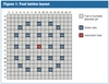
The 17x17 lattices include several types of pins (Figure 1):
1. UO2 fuel pins of different enrichments: variable number of pins per lattice
2. Integral burnable poison fuel pins, UO2–Gd2O3, of different enrichments and Gd2O3 concentrations: variable number of pins per lattice
3. Burnable poison pins (BPR), of different absorber concentrations: variable number of pins per lattice
4. 24 guide tubes (non fuel): fixed number per lattice, and
5. One central instrument tube.
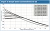
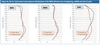
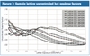
The fuel lattices were designed so that the radial pin-by-pin power distribution (peaking) within the lattice, as well as the reactivity changes with time (lattice k-inf) will be as flat as possible. The pellet enrichments employed in the mPower fuel design are standard pellet enrichments used in the nuclear commercial world, with U-235 wt% up to 4.95. The gadolinia concentration in the UO2-Gd2O3 fuel pellets is also the same as other commercial nuclear power plants use, with Gd2O3 concentrations up to 6%. End lattices are lower enriched, but not natural blankets.
A flat pin-by-pin power distribution ensures a more evenly burnt fuel, whereas a flat lattice reactivity allows core operations with minimal control rod adjustments (Figures 2 & 3).
Fuel pins may have axially varying Gd2O3 content and BPR pins may have axially varying poison content, but UO2 and BPR materials are never combined in a single pin. The number, layout and content/enrichment of the fuel rods and burnable poison rods are specific to each neutronic fuel type. Several combinations of different fuel pin enrichments and poison concentrations and number of burnable absorber pins were used in the B&W mPower fuel assembly design to extend the overall cycle energy, to optimize safety parameters and to maximize fuel utilization.
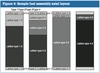
Fuel assemblies (several types) were developed and loaded in the reactor core in an eighth-symmetric manner and further optimized to work in concert with the control rod sequences and to fit the specific axial and radial conditions of their location in the core. Figure 4 presents schematically the B&W mPower fuel assembly design philosophy.
Core loading pattern
The fuel assemblies are loaded in the reactor in a manner consistent with the assemblies’ axial design, so that they perfectly fit the specific radial conditions of their location in the core and they provide the maximum benefit from cycle energy and fuel utilization point of view, without any impact on safety parameters. The loading of the B&W mPower fuel, as described in this report, results in a projected cycle full power energy capability of about 725 GWd (36.75 GWd/MTU). Beyond the full power capability, the B&W mPower core can achieve some 10 GWd of additional energy via power coastdown operation, for a projected EOC core burnup of 37.25 GWd/MTU.
Reactivity management strategy
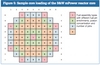
During normal reactor operation control rods are inserted to balance the excess reactivity in the core. When inserted, a control rod assembly perturbs the local power shape; subsequently, the exposure accumulation will differ between neighbouring fuel assemblies as well as between different axial nodes of the same fuel bundle. When previously controlled nodes are again ‘uncovered’, the fuel pins will run at higher peaking factors than in an uncontrolled scenario, and at an increased local heat generation rate. The magnitude of the peaking depends on the length of the control interval, the frequency of the control intervals and the lattice design.
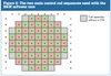
To minimize these negative aspects, the control rod history effects can be minimized by reducing the control frequency and the exposure interval over which a fuel node/assembly is controlled. For this purpose, the CRAs were grouped in a manner similar to that in a BWR core into two main control rod patterns, A and B, distributed in a checkerboard pattern, as shown in Figure 6. Several control rod sequences are used throughout the cycle, so that each bundle is controlled (totally or partially) for a total of approximately six months out of the cycle.
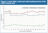
The axial and radial power and exposure distributions, along with the core axial offset and the nodal and radial peaking factors are means to assess the core performance and margin to safety limits. It is always desired that the axial and radial distributions of parameters that show the performance of the core, quantitatively and qualitatively, be as flat as reasonably achievable. Axial offset (core average) is defined as the percent difference between the power generated in the upper and the lower halves of the core:
Axial Offset = (Pt – Pb) / (Pt + Pb) × 100
where Pt and Pb are the integrated powers (sum of calculated nodal powers) in the top and bottom halves of the core, respectively.
Nodal peaking values represent the highest bundle planar power, at a given exposure, normalized to the core average power. Since a fuel lattice is defined with four nodes, the planar bundle power represents the ‘collapsed’ power in the four nodes. Figure 7 summarizes the axial offset and the radial and nodal peaking factors of the B&W mPower reactor core throughout the cycle.
Figure 8 illustrates the axial power and exposure distributions at three points in core life: beginning (BOC), middle (MOC) and end of cycle (EOC).
The shutdown margin (SDM) is defined as the amount of reactivity, expressed in %?k/k, by which the reactor is subcritical with the analytically determined maximum worth control rod assembly assumed stuck in the fully withdrawn position and all other assemblies fully inserted. The cold shutdown margin (CSDM) is the level of core subcriticality at 68°F (20°C), atmospheric pressure and xenon-free conditions (the three parameters that define the ‘cold’ state) with the strongest CRA out. CSDM is calculated with SIMULATE-3 by running one-rod-out cases, at cold conditions, restarting from the desired statepoints (exposures) in the nominal cycle run. CSDM is highly dependent on the local conditions surrounding the CRA which is assumed to be fully withdrawn. Therefore, CSDM is usually loading pattern dependent. For the B&W mPower reactor, the CRAs with the highest worth under cold conditions at BOC are located in the fuel assemblies type 3, making the core periphery CSDM limiting at BOC. For an established operating plant with benchmarked physics, the standard industry minimum accepted value for CSDM is 1%?k/k; however, the B&W mPower core was designed so that at least a minimum of 3%?k/k margin to cold shutdown is maintained at all times. The minimum CSDM occurs at BOC and it is above 4%?k/k. Figure 9 summarizes the cold shutdown margin of the B&W mPower reactor core throughout the cycle.
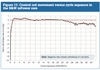
The hot excess reactivity (HEX) is the amount of reactivity that must be controlled at normal full power operating conditions using control rods. The higher the hot excess reactivity, the greater the control rod density needed to maintain the reactor at the full power critical state. Too much HEX is disadvantageous, since it would require high control rod densities to control the reactivity. Too little HEX is also undesirable, because it may leave the core with limited capability to overcome xenon transients during power manoeuvres. In any case, HEX eigenvalue needs to be greater than 1 in order to maintain a 100% power level (HEX eigenvalue < 1, or HEX < 0, during coastdown). HEX is defined as the amount of reactivity, expressed in %?k/k, by which the reactor would exceed criticality if all CRAs were withdrawn at rated conditions. HEX is calculated with SIMULATE-3 by running ‘all rods out’ (ARO) cases, at rated conditions, restarting from the desired statepoints (exposures) in the nominal cycle run. Unlike the cold shutdown margin, hot excess reactivity is a core-wide phenomenon.
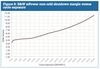
Figure 10 summarizes the hot excess reactivity of the B&W mPower reactor core throughout the cycle.
Control rod movement is calculated as centimetres of control rod length inserted (+) or withdrawn (–) in a day and is determined based on initial and final control rod position during a control sequence (or sub-sequence) and assuming continuous adjustment of the ‘floaters.’ The B&W mPower core design, with its ‘flat’ hot excess reactivity, allows power operations with very little reactivity control adjustments. Figure 11 summarizes the B&W mPower reactor fine-motion control rods movement throughout the cycle.
The cycle management plan is flexible in that it can accommodate target eigenvalue biases of several milli-? in both the positive and negative directions. In other words, the same rod pattern concept (that is, sequence) provides for acceptable power tilts and peaking over a range of target eigenvalues. However, there is a limit to the amount of reactivity bias that can be accommodated by a cycle management plan before the rod patterns degenerate. Analyses performed showed that the cycle management plan cannot accommodate, ‘as is’, a reactivity bias of 10 milli-? in the more reactive direction. An alternate cycle management plan was developed to accommodate this hopefully unrealistically large bias, with no negative impact on safety limits. Since cycle management plans are integral with a licensed core design, the customer would not be allowed to proceed with alternate rod patterns unless supporting licensing analyses were performed. The analysis was intended to show that the core design is robust, in that it is not precariously dependent on exact rod patterns. In this scenario, the cycle would gain approximately 1.0 GWd/MT in energy; this translates into approximately 40 EFPD (over a month of full power operation). Conversely, analyses performed for the other direction of a hypothetical bias in core reactivity showed that, with minimal alterations, a reactivity bias of 10 milli-? in the less reactive direction can be easily accommodated (as expected). Supporting licensing analyses should also be performed, although this scenario would raise fewer safety concerns. In this scenario, the cycle would lose 0.5 GWd/MT in energy; this translates into a reduction of approximately three weeks of full power operation.
Conclusions
The design of a fuel cycle is an iterative process between the lattice/assembly design and the core loading/cycle management design. Failure to meet certain safety criteria (CSDM, nodal peaking, and so on) or design goals (cycle energy) leads to the redesign of certain lattices and fuel assemblies. The fuel assembly design was performed by iterating on nuclear parameters, both at lattice level and at assembly level. Lattice data libraries were created, specific lattices were assigned to specific elevations in fuel assemblies and specific assemblies to certain locations in the core; then the in-core performance of the fuel assemblies was analyzed.
Since the B&W mPower reactor, although pressurized, is unborated, and core reactivity and margins to safety limits are controlled with rods, some core parameters tend to become more localized then they are in a typical, currently-operating PWR. One significant example to illustrate this point is the cold shutdown margin, a strongly localized phenomenon. One other example is the evolution throughout the cycle of the core axial offset. The way to balance or counteract some of these localized effects is to design optimized sets of lattices (that is, optimized fuel assemblies) which will best fit certain locations in the core. For instance, core locations that are known to be limiting for CSDM will require fuel assemblies that are (or can be made) less reactive. This could be achieved by either decreasing the enrichment or increasing the neutron poison composition in those (or adjacent) locations. Since decreasing the enrichment would impact (lower) the EOC energy, the obviously better choice is to increase the neutron-absorbing capability of certain lattices in limiting locations.
The B&W mPower core axial offset (A-O) presents a natural tendency to be positive towards EOC. It is determined throughout the cycle by the management of the control rod sequences (axial insertion and CRA radial position in the core). But, although the B&W mPower reactor will always be top-peaked at EOC, since all the rods are fully withdrawn at that point, optimizing the design of the lattices located at the top of the fuel assemblies greatly reduced the EOC top peaking.
The lattices and bundles designed for the B&W mPower core meet the energy requirements and safety limitations imposed. CASMO-5 output files were used to analyze fuel nuclear characteristics on an infinite lattice basis. Further, with SIMULATE-3, all fuel assemblies were analyzed on an in-core location basis (nodal parameters, pin-by-pin values, etc.). The reactor core and cycle management simulation confirmed that the fuel satisfies the constraints and requirements of the cycle for which it was designed. Not least, Studsvik methods accuracy was benchmarked for different loading configurations – involving, among others, fixed burnable poison rods, heterogeneous clean loadings as well as UO2-PuO2 configurations. Eigenvalues and localized pin power distributions within a fuel assembly, calculated using CASMO-5/SIMULATE-3, were compared to the measured results from the respective experiments, with very good agreement of data.
Related Articles
B&W’s baby
B&W unveils its new modular reactor
Bechtel joins B&W 125MW mPower project
B&W to open mPower test centre in Virginia
GSE selected for mPower simulator
This article was first published in the October 2012 issue of Nuclear Engineering International. It is based on a paper presented at PHYSOR 2012, Knoxville, Tennessee, USA, 15-20 April 2012.
Madalina Aimee Erighin, The Babcock & Wilcox Company, 109 Ramsey Place, Lynchburg, VA 24502, maerighin@babcock.com
The author would like to give thanks to Dr. Gary W. Neeley for suggestions, as well as for providing critical review of this work and its conclusions. This analysis was built upon the initial nuclear lattice design work performed by Dr. Dudley A. Raine for the B&W mPower reactor extended once-through fuel cycle. Valuable input, suggestions and contributions were provided by Michael J. Scarangella, by sharing several fuel lattice designs that were very useful in the initial core loading (cycle 1). Dr. Stephen W. Scoles and Joseph S. Divoky provided the most valuable feedback and review of the B&W mPower core design from their thermal-hydraulic analysis perspective. Dr. Eric A. Barringer's contribution, from his fuel assembly mechanical design view point, was also greatly appreciated.
References
[1] "CASMO-5/CASMO-5M - A Fuel Assembly Burnup Program User's Manual", SSP-07/431, Rev. 1, Studsvik Scandpower, July 2010.
[2] "CMS-LINK User's Manual", SSP-07/431, Rev. 2, Studsvik Scandpower, April 1999.
[3] "INTERPIN-4 User's Manual", SSP-07/435, Rev. 0, Studsvik Scandpower, October 2007.
[4] "SIMULATE-3 Advanced Three-Dimensional Two-Group Reactor Analysis Code", SSP-95/15, Rev. 4, Studsvik Scandpower, September 2007.
[5] "B&W mPower Reference Fuel Assembly Design and Lattice Physics Analysis Report", Babcock & Wilcox Company, July 2012.
[6] "˜B&W mPower Reference Core Loading and Cycle Reactivity Management Report", Babcock & Wilcox Company, July 2012.
[7] "Core Nuclear Design Codes and Methods Qualification Topical Report", The Babcock & Wilcox Company, September 2010.