Inspection
Core vibrations
15 July 2004A miniature biaxial in-core accelerometer was successfully used to detect impacts and to localise the radial and axial position of impacting components inside the reactor pressure vessel of two 1300MWe BWRs during full power operation.
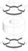
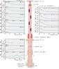
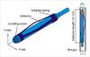
A miniature biaxial accelerometer was developed for acceleration measurements in radioactive and high temperature environments by Vibro-Meter. In cooperation with the Institute of Nuclear Engineering and Nondestructive Testing at the University of Hannover, a special version of the sensor, which can be inserted inside the travelling in-core probe (TIP) tubes of nuclear power reactors instead of the TIP, was developed. The geometrical dimensions of the accelerometer and the TIP are similar, therefore the accelerometer can be moved in the same way as a TIP. The coupling between the transducer and the inner wall of the tube is performed by means of a specially designed adapter spring (see Figure 1).

Gundremmingen
SENSOR DESIGN
The design of the biaxial accelerometer is effectively imposed by the geometrical envelope permitted, ie that it should be attached with the longer axis parallel to the tube that needs vibration measuring. This means that the transducer is sensitive in x and y directions and without sensitivity in the z axis where the length is relatively unimportant. The biaxial accelerometer works in the so-called ‘bender’ mode patented in 1992.
The whole assembly, consisting of transducer head and spring, does not have sharp edges and is designed to be easily moved forwards and backwards instead of the travelling neutron probe inside TIP-tubes. The sensing elements (see Figure 2) are using the piezoelectric effect to measure vibrations. The charge output of a piezoelectric ring is proportional to the dynamic compression applied to it. The piezoelectric stack is held together by means of a pre-stressed rod. On the top of it there is a seismic mass fixed to the piezoelectric stack.
In order to obtain a sufficient sensitivity the number of crystals together with the total seismic mass operating on them has to be optimised. The total mass working in the crystal stacks is composed of a high density material (tungsten) in order to get the maximum mass within the minimum volume. The whole sensing element is bound together under a high pre-stress so that no parts may move with respect to each other especially under the maximum shock that is encountered. It is essential that the pre-stress does not sensibly change with temperature, which necessitates the incorporation of a thermal compensation material to match the rates of expansion between the diverse parts within the sensing element and the pre-stressed rod. Under the influence of inertial forces which act perpendicular to the axis of the pre-stressed rod, seismic mass bending load occurs which results in an increase of the compression at one side and in a decrease of the compression at the other side of the piezoelectric rings.
Each piezoelectric ring has a four-segment electrode mounted on its top face and a four-segment electrode mounted on its bottom face. The opposite pairs of segments are connected together so as to provide a biaxial accelerometer. The integrally attached hard-line cable compromises a MgO insulation and four conductors which are connected to the electrically separated sensing elements. The choice of the piezoelectric material is driven by the operational temperature, the radiation and the design itself which requires very homogenous and stable materials. The natural hydrogen piezoelectric crystal defined as ‘Vibro-Meter VC2’ was chosen so far. Although this material has been found not linear in terms of sensitivity under high radiation at low frequencies (see next section), the previous applications show that the biaxial accelerometer can be successfully used for acceleration and vibration measurements inside operating power reactors. Further developments will be in finding the best piezoelectric material for the application and its evaluation under high radiation.
LOW FREQUENCY VIBRATION MEASUREMENTS
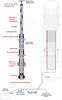
The vibrations of BWR internals were analysed in low frequency range (below 10Hz) by use of the simultaneously measured signals of in-core neutron detectors and the in-core biaxial accelerometer. The latter was temporarily positioned at the neutron detector height inside several instrumentation tubes during full power operation. The biaxial sensor could be moved inside the TIP tube to any position up to the upper core grid (see Figure 3). It was inserted in the TIP tube at the position of the cable reel and pushed with the cable itself. Pre-operational tests in a full scale model of the TIP system have been performed for the successful optimisation of the adapter spring, which must be weak enough so that the detector can be moved and strong enough so that the coupling force is sufficient to measure the tube vibrations in the frequency range of interest (up to 1 kHz for impact detection).
The normalised auto power spectral densities (NAPSD) of in-core neutron noise signals, measured in one of the 42 instrument strings of the BWR (see Figure 4, top of right side) show a significant peak at 2.5 Hz. It is known that this peak is caused by a vibration of the instrumentation tubes between the upper and the lower core grid, without impacts or contacts of the guide tube to the surrounding fuel channel boxes. The corresponding APSDs of the accelerometer signals (Figure 4, left side) have a similar shape at the measuring positions inside the core, while they deviate as expected at measuring positions below the lower core grid and outside of the reactor pressure vessel. The amplitudes of the movements can be inferred from the acceleration signals by double integration in time domain as well as in the frequency domain and from the neutron noise spectra through neutron mechanical scale factors relating the random displacements to the relative change of the neutron signal. From the APSD of displacement the root mean square (RMS) value in x and y direction and the resulting vector can be calculated.
The procedure of calculation of the RMS is based on integrating the shape of a peak given by a linear vibration equation, but the effect of non-linear sensitivity of the accelerometer in the low frequency range and under the influence of radiation has to be considered. The resulting RMSx,y has the dimensions of mm. The RMSn value of neutron signals is calculated from the NAPSD in the same frequency range correspondingly. For correlated acceleration and neutron noise signals, neutron-mechanical scale factors for different vibration modes of BWR instrument tubes (at 1.6Hz and at 2.5Hz) and for a combined vibration of instrument tubes and fuel channel boxes at approximately 4Hz were determined. The displacements of the corresponding vibrating components inside the core of the given BWR can then be estimated through the scale factors from the neutron noise spectra of signals measured by the standard in-core instrumentation. For a PWR application there have been published some corresponding results.
Under the influence of the high radiation inside the core a remarkable increase of the measured amplitudes of the acceleration signals was observed in the low frequency range (see Figure 5). This reversible, frequency and radiation dependent sensitivity change of the biaxial in core accelerometer had not been fully understood until now. But the effect must be taken into account and corrected for the determination of the scale factors.
Further investigations will be done to find new piezoelectric materials for the specific application in high radiation and high temperature environment in order to determine and minimise the radiation influence to the low frequency signal of the in-core accelerometer.
DETECTION OF IMPACTING TUBES
The vibrations of all in-core instrumentation tubes of both units of Gundremmingen are frequently analysed twice in each fuel cycle by use of neutron noise analysis. Particular vibrations of single instrument strings were found and monitored subsequently. The instrument tube vibrations and the effect of possible impacts to surrounding structures on the vibrations were analysed and analytically modelled. The theoretical results were used to interpret the particular instrument tube vibrations. This interpretation gave some indication that impacts of at least one of the instrument tubes against the surrounding structures occurred. A detailed inspection of the relevant tube during a subsequent regular shutdown was made, and it was found, that the instrument guide tube was damaged at the position of the mounting bell (see Figure 3) and that flow induced impacts of the three telescoped tubes of that particular instrument string had caused a degradation of the structure in the area of the mounting bell.
In order to detect even weak impacts, which might not influence the vibrations of the instrument tubes inside the core region and which therefore cannot be detected by neutron noise analysis, the new biaxial accelerometer has been inserted in all TIP tubes during full power operation.
In the frequency range up to approximately 1 kHz (due to the sensor construction and the adaptation by a spring this is the maximum frequency of the measuring system) flow induced impacts of some other in-core instrument tube structures were also localised.
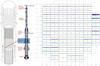
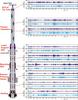
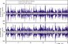
The acceleration signals (x- and y-direction) measured inside of the TIP tubes at the mounting bell position of all instrument strings are shown in Figure 6 in time domain. In a few core position bursts, caused by impacting structures, are clearly visible. At those core positions, the biaxial in-core accelerometer has been moved to several axial positions up to the upper end of the TIP tube, in order to localise where the impacts were transmitted to the TIP tube. In Figure 7 some examples of these measurements in one of the instrument strings are given.
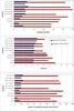
Comparing the signals in Figure 7, it cannot clearly be seen in which axial position the strongest bursts are measured. In order to indicate the position where the impacts are created, statistical values of the acceleration signals were calculated and some of the results are in Figure 8. The standard deviation (Figure 8, upper part) characterises the energy content respectively the averaged amplitudes of the signals. The Kurtosis factor (Figure 8, middle part) is used to quantify the burst content of the signals. If the signal fluctuations are normally distributed and are not influenced by bursts, then the value of the Kurtosis factor is three, while bursts cause an increase of it. For weighing the energy and burst content of the measured acceleration signals we defined the product of the standard deviation and of the kurtosis factor as an intensity value of possible impacts.
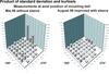
The comparison of the statistical values calculated from measured acceleration signals at several positions inside a single TIP-tube before and after the guide tube has been sleeved shows relatively high standard deviations and consequently relatively high intensity values (product of standard deviation and Kurtosis factor) in the core region (Figure 8). This is caused by the obvious increase of the sensitivity of the biaxial accelerometer when it was exposed to the high flux inside the core. But this has no influence to the Kurtosis factors, which show a relative maximum in the axial vicinity of the in-core instrumentation guide tube mounting bell where the impacts happened. Obviously the bursts were transmitted from the guide tube to the inner TIP tube through the water inside the gaps between the telescoped tubes. This enables the localisation not only of the radial but also of the axial position where fretting or impacting of instrumentation tube components or other structures might occur inside the reactor pressure vessel and core.
The German company Siemens KWU developed the technology to strengthen the impacting tubes by special sleeve tubes inside the instrument guide tube at the position of the mounting bell. The sleeves were mounted during regular outages of the plants. After restarting it could be verified by repetitive reactor external and internal acceleration measurements, that the impacts have been reduced drastically due to the improvement of the construction (Figure 9). After this improvement the Kurtosis factors calculated from the acceleration signals measured at the same positions as before (Figure 8) still show a maximum at the mounting bell position, because weak impacts were registered after strengthening the guide tube, but the intensity values demonstrate the remarkable reduction of the impact energies.
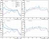
In Figure 10 the impact intensity values of all in-core instrument tubes measured at the axial position of the guide tube mounting bell are compared before and after strengthening two of the guide tubes (those which had the highest values before). It is clearly seen, that the sleeves reduced the impact intensity at these positions and that the intensity did not increase at other positions, where low intensity was detected previously and consequently no sleeves has been mounted. Repetitive measurements of the in-core acceleration inside all of the TIP-tubes allows the early detection of degradation due to fretting and impacting. The efficiency and long-term performance of subsequent improvements (sleeves) can be controlled with high local resolution and sensitivity.
Author Info:
J Runkel, D Stegemann, J Fiedler and P Heidemann, Institute of Nuclear Engineering and Nondestructive Testing, University of Hannover (IKPH), Elbestr. 38 A, D-30419 Hannover, Germany; R Blaser and F Schmid, Vibro-Meter SA, P.O. Box 1071, CH-1701 Fribourg, Switzerland; M. Trobitz, L. Hirsch and K.Thoma, Nuclear Power Plant Gundremmingen (KRB), P.O. Box 300, D-89355 Gundremmingen, Germany