Decontamination system starts up for unit 2 spent fuel pool

16 November 2011


TEPCO has launched a radiological decontamination system for the unit 2 spent fuel pool. TEPCO said that the system needed to start before a desalination system that is also planned, since highly radiological concentrated seawater is difficult to treat.

Pulverised unit 4 fourth-floor air conditioning ducts

The system takes water from the circulating cooling system installed earlier this year (after the heat exchanger), and passes it through a truck-mounted valve unit, a truck-mounted caesium adsorption tower, and returns the water to the cooling system line before heat exchange. The system is truck-mounted to save space. It is expected to reduce the level of caesium by 100-1000 times.

TEPCO chose unit 2 because it has the highest radiological contamination level; 120,000 Bq/cc of caesium-134 and 110,000 Bq/cc of caesium-137. That level is about two-thirds higher than unit 3's spent fuel pool, and 5-10 times the levels of unit 1's, according to sampling data taken in August and September. The unit 4 spent fuel pool water had much lower radiation levels: 120 Bq/cc and 8.2 Bq/cc.

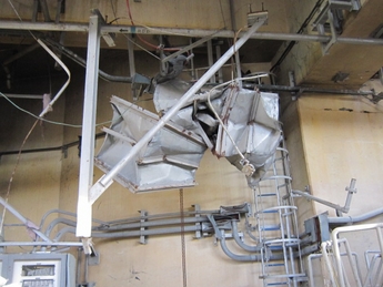
An investigation team has ventured into the unit 4 reactor building to gather evidence to determine the cause of the 15 March explosion in unit 4. The dominant hypothesis currently is that hydrogen generated in unit 3 flowed backwards up unit 4 air-conditioning ducts and flowed into the unit 4 reactor building. The team drew one firm conclusion: that the explosion likely occurred mainly on the fourth floor of the building, for two reasons: the fifth floor deck was pushed up and the third floor deck was pushed down, and because wire mesh attached to fifth floor air conditioning inlets were bent in the reverse direction of air flow. On the fourth floor itself, all of the air-conditioning ducts had been pulverised and scattered over the floor, suggesting that it was possible that the explosion occurred around them.


JANTI report recommendations

1. Power sources
Installation of seawalls or tide embankments for important safety equipment
Preventing against inundation of sections where important safety equipment is installed
Preventing against inundation including improving seals around penetrations and air inlets and other openings in proportion to the height of inundation
Development of watertight locations for deployment of power receiving transformers and switchyards or measures to prevent against inundation of equipment
Development of watertight locations for deployment of DC power supply equipment or measures to prevent against inundation of equipment
Deployment of power generating cars or large capacity power supplies (gas turbines and diesel generators), and development of procedures for emergencies
Development of routes for recharging DC power supplies by means of backup power sources
Improving reliability through measures to prevent against inundation of equipment for interchanging power sources between units (severe accident measure)

2. Heat sinks (coolant injection and cooling)
Bulkheads around seawater pumps and other inundation protection measures
Deployment of spare parts for seawater pump motors
Deployment of mobile seawater pumps
Preventing against inundation of sections where the emergency core cooling systems and other safety system equipment are installed
Measures to prevent against inundation of equipment for severe accident measures
Backup power supplies, standby air cylinders and other preparations for SRV drives (BWR)
Ensuring core cooling via SG by means of the main steam relief valve (PWR)
Deployment of backup power sources and driving sources for venting operations (BWR)
Improving reliability of existing coolant injection systems through deployment of backup power generating cars or large capacity power supplies
Movable pumps, hoses, etc. not dependant on existing equipment
Securing water supplies
Releasing heat into the atmosphere through containment vessel venting (BWR)

3. Measures to protect against hydrogen explosion
Releasing and reducing retained hydrogen
Measures to prevent against inflow from pressure strengthened venting lines
Preventing hydrogen from circulating around between units having a common exhaust stack


FilesReactor-by-reactor Fukushima Daiichi restoration progress summary as of 17 November, from JAIF
INPO Fukushima event report
JANTI report: summary
JANTI report: full text


Privacy Policy
We have updated our privacy policy. In the latest update it explains what cookies are and how we use them on our site. To learn more about cookies and their benefits, please view our privacy policy. Please be aware that parts of this site will not function correctly if you disable cookies. By continuing to use this site, you consent to our use of cookies in accordance with our privacy policy unless you have disabled them.