Research reactors
US veteran gets a facelift
19 January 2012Idaho National Laboratory’s Advanced Test Reactor (ATR) has received replacement instrumentation and control systems—the process distributed control system (DCS) and the console display system (CDS), which included a replacement annunciator subsystem. The new systems offer the latest software and technology advancements, ensuring the availability of the reactor for future energy research. By Craig Wise, Gary Bergeson and Kurt Fielding
ATR, a pressurized, light water moderated 250 MW materials test reactor, became operational in 1965. In the early 1990s, after nearly thirty years of analogue/pneumatic controls, the laboratory upgraded ATR to digital-based instrumentation and control systems. By 2007, the equipment and technology used in these digital systems were reaching the end of their lifecycle. The systems’ component failure rates were on a rise, while vendor support and parts availability were declining.
With current projections and plans for operating ATR into 2040, modernization of the reactor’s infrastructure is necessary to maintain reliability and efficiency. As a result, the Idaho National Laboratory and the U.S. Department of Energy (DOE) invested more than $13 million in a four-year project to replace ATR’s instrumentation and control systems.
Distributed control system (DCS)
The DCS is the heart of the instrumentation and control system, providing automatic, closed-loop control functions, manual control functions from DCS operators, and parameter display functions. For example, this control system maintains the reactor’s core temperature by monitoring and automating the flow of the primary and secondary coolant pumps. In addition, the DCS automates control of the reactor’s coolant level, the heat exchangers, cooling tower fans, waste flow, vessel seal, and other important subsystems. The size of the ATR DCS is defined by the number of supported data points, which is in the 5,000 to 10,000 class size.
Functionally, the replacement DCS was required to have like-for-like duplicate controls. For example, the closed-loop functions in the predecessor DCS, such as reactor vessel pressure control, were typically accomplished using Proportional, Integral, Derivative (PID) closed loop control algorithms. As a result, the performance characteristics of the old DCS design, including the details of the PID algorithm and the associated PID control parameters (variables), were carefully replicated in the replacement DCS environment. Using like-for-like replacements helped to ensure that the new systems presented minimal safety risks to the reactor operators. Even the replacement DCS’s control pop-up windows were required to match the functional details of the previous system as much as possible.
Other DCS enhancements included a dual-redundant Ethernet network. The predecessor system relied on a token ring, fibre optic network. While this ran well in the beginning, the network equipment had begun to degrade, causing the token ring network to become less reliable and was inherently difficult to troubleshoot. In addition, data archiving for the system used obsolete storage media—WORM (write once read many) optical disk technology.
The replacement DCS was purchased from Metso Automation and is composed of the following major components:
- Dual-redundant ethernet network: The DCS network operates at 100 Mbps and is based on the switched fast ethernet standard. Exclusive to the DCS, the network interconnects all DPU, workstation, and peripheral equipment. The entire network is redundant with instantaneous switchover to the backup, resulting in no single point of failure.
- Workstations: Each workstation consists of a rack-mounted computer running Microsoft Windows XP. There are three types of workstations: operator, engineering and historian. Each type provides a different view of the processes being controlled and monitored by the DCS.
- Distributed Processing Units (DPUs): The DPU is a multifunction controller and data acquisition processor that executes control algorithms, sequence logic, comprehensive alarming, continuous scanning of Input/Output (I/O) modules, and sequence of events recording. The DPU is the main processing engine of the DCS and runs under the Windows CE.net multitasking operating system. The control processor is a Pentium-class National Semiconductor Geode CPU.
- Input/Output Modules: I/O modules connect the hundreds of process variables and controllable end-element devices throughout the plant to the DCS. The I/O modules used in the ATR DCS include high level analogue input and output, +24 VDC digital input, 120 VAC digital input, relay output, thermocouple input, and resistance temperature detector (RTD) input.
Console Display System
The CDS is the interface system for displaying information from the reactor’s data acquisition computer system, which continuously monitors over 500 points of data during reactor operation. The CDS displays data from several important reactor systems including the plant protection system, reactor power split calculation, fission break, and control rod panel indications. The annunciator system monitors the same systems through the sequence of events recorder (SER) to provide critical alarms to the reactor operators. Should any of the reactor’s systems function in a way other than as expected, the monitoring CDS displays the system data while the annunciator system alerts the operator to alarm conditions.
Both the CDS and annunciator systems were purchased from Rolls Royce (formerly Data Systems & Solutions), and both systems were designed with an eye toward the future—they remain open enough to incorporate future improvements and system updates.

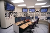
The graphical displays were greatly improved—for example, the annunciator system went from nine outdated light boxes to four 52-inch LCD screens with colour-coded alarm displays. However, the team ensured that the user interface maintained the same general layout as the previous systems. In this way, very little re-training was required for the reactor operators.
The ATR CDS consists of two servers to acquire the data and seven operator workstations. In addition, the CDS is composed of a dual redundant network, alarm and display management computers, configuration workstation, printers, a fully redundant SER data acquisition system, and the alarm display computers and monitors.
- CDS Servers: There are two servers in the ATR CDS that operate in primary and standby configuration. Each has a dual CPU Quad-Core Xenon 2.38 GHz processor, and both are equipped with two 250 GB SCSI disk drives configured in a RAID 5 set, which ensures the plant monitoring system (PMS) database is fault tolerant in the event one hard drive fails. The computers use the Windows Server 2008 operating system. Each of these servers acquires data from its associated reactor data acquisition system (RDAS) computer as well as from the annunciator system SER on the data network.
- CDS Workstations: The seven Systel workstations have a single CPU Intel Quad-Core Xenon 2.0 GHz processor with 8 Mb cache. Each workstation is equipped with one 80 GB SATA disk drive. The computers use the Windows XP PRO operating system. Display data to these workstations is provided by the CDS servers across the human-machine interaction network.
- Annunciator Servers: There are six independently-functioning Systel servers in the ATR annunciator system. Each has a dual CPU single Core Xenon 2.0 GHz processor, and all are equipped with two 80 GB SCSI disk drives configured in a RAID 1 set. The computers use the Windows Server 2008 operating system. Each of these acquires data independently from the annunciator system SER across the data network and can be configured to display any of the annunciator display screens.
- Sequence of Events Recorder (SER): The fully redundant SER receives digital alarm signals from the ATR plant, timestamps changes, and transmits the event messages to the CDS and to the annunciator servers. The SER is capable of acquiring at least 512 digital points and timestamp alarm events at 1 ms resolution at a sustained rate.
Project schedule
ATR engineers began the initial phases of the replacement project by establishing the need for replacement DCS and CDS equipment. The mission need document was prepared and approved by DOE in May 2007.
As a federal research and industrial complex, the Idaho National Laboratory and the DOE worked very closely during every phase of the replacement project. Each critical decision and project plan developed by the laboratory was carefully reviewed and regulated.
Following approval of the mission need document, Idaho National Laboratory and ATR were provided initial project funding and the replacement project team was established. The laboratory appointed Bill Steele as the project manager to oversee two separate teams: the DCS replacement team and the CDS/annunciator system team. Each team included six engineers. Both teams worked for more than 12 months developing acquisition strategies, conceptual design plans, cost estimates, and a preliminary project execution plan. Procurement contracts for the new CDS and DCS were awarded in the spring of 2009. A final project execution plan was issued to DOE in September 2009. The final plan included a refined cost estimate with detailed activity duration and resource estimating. The final plan also included vendor design drawings for the procured equipment/software systems, preliminary ATR facility installation design drawings, and updated technical and functional requirements documents.
None of the systems replaced by this project are relied on as reactor safety systems. However, some of the functions they provide are used for safety-related activities, such as surveillances. During the project development phase, all safety-related functions associated with each system were identified and documented in the systems’ technical and functional requirements documents. All system requirements were then tracked and verified to be implemented and tested using a project requirements traceability matrix (RTM). Each vendor also used their own RTM to ensure proper coverage of all requirements given to them. This ensured that requirements were correctly implemented in the replacement systems during several project stages.
In order to achieve the software reliability and quality control required by nuclear digital process controls, the ATR team created a complete system test bed in 2009. The test bed utilized reactor modeling programs borrowed from the ATR training simulator facility to create a virtual reactor. The virtual reactor’s modeling programs simulated real-time scenarios in which the new control systems’ could be exercised and tested. ATR system engineers worked closely with the vendors, using the test bed to identify errors early in the software design phase of the project and sending any issues back to the vendors’ development teams for resolution. This was a huge benefit that identified and eliminated errors long before the systems were deployed.
Vendor factory acceptance testing of the systems was performed between April and June 2010; their shipments of equipment to ATR began that May. In addition, both vendors provided detailed engineering, operations and maintenance training.
In the year leading up to final implementation, ATR engineers updated more than 230 operations procedures and wrote more than 40 new system operability test procedures. More than 400 drawings and illustrations were created or modified to support the documentation.
Implementation
Pre-implementation preparations expedited the final plant installation process. These preparations were completed between November 2009 and September 2010 during the six outages prior to the final equipment installation.
Preparation included floor penetration surveys to map embedded rebar and conduits; fabrication and installation of seismically-qualified server cabinet stands; installation of new seismically qualified conduits; installation of DCS I/O modules; pulling and termination of new wire cables and optical fibres; and moving panel equipment that would interfere with new 52-inch annunciator display monitors. All preparatory equipment installation work was accomplished without impacting the reactor’s scheduled system operation.
The replacement DCS and CDS were installed in ATR’s simulator training facility before they were installed in the ATR. This facility provides a full-scale replica of the ATR control room that mimics the response of the reactor, duplicating functionality of the CDS, DCS, and alarm systems. Within the ATR simulator, the DCS received a notable enhancement. The new simulator DCS now uses virtual distributed processing unit (vDPU) technology, which simulates the reactor’s multiple DPUs with a single, high-powered computer. Since the reactor modeling computer now is able to transmit all I/O points directly to the vDPU computer using one network connection, thousands of discrete I/O points have been consolidated. Installation efforts for the simulator began in June and were completed by September 2010.
Once the DCS and CDS were installed in the simulator, the replacement team began operations training, which included hands-on experience with the new systems. Additional training efforts included the preparation of training design plans and course presentations along with classroom training and practical exercises. Training of ATR operations and maintenance personnel began in October 2010 and continued through February 2011.
Replacement efforts within the ATR reactor control room and plant for the DCS and CDS systems were performed during a scheduled outage that began in January 2011. These efforts included five major phases: equipment removal and installation; post-installation testing; individual systems operability testing; integrated system operability testing; system turnover to ATR operations.
To verify the reactor’s readiness for each of the phases outlined above, management self assessment reviews were conducted in accordance with DOE regulations. Once each phase had been completed satisfactorily, engineers and operators successfully started the reactor using the new instrumentation and control systems in March 2011.
“The latest investment at ATR increases the plant reliability and safety,” said Mike Love, Director of ATR Operations. “In addition, these state-of-art control systems increase the capabilities of our operators, so we can continue assisting universities and private agencies with their research.”
Following reactor startup, the project closeout phase included resolving any post-start system issues, updating system documentation, finalizing system drawings, performing final software quality assurance assessments, and warehousing spare parts for future needs. All project closeout activities were completed by September 2011.
This article was first published in the December 2011 issue of Nuclear Engineering International magazine (p32-34).
Author Info:
Craig Wise, Gary Bergeson and Kurt Fielding, Idaho National Laboratory, 2525 Fremont Ave, Idaho Falls, Idaho, 83415 USA
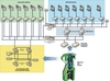
| How the Advanced Test Reactor works |
| The physical design of the ATR's serpentine core configuration of 40 fuel assemblies allows the core lobes to be operated at different powers and to offer numerous experiment positions with variable conditions for multiple simultaneous experiments. Neutron flux in the ATR varies from position to position and along the vertical length of the test position. It also varies with the power level in the lobes closest to the irradiation position. The curved fuel arrangement of the ATR places reactor fuel closer on all sides of the flux trap positions than is possible in a rectangular grid. The unique core design of ATR control devices permits large power variations among its nine flux traps using a combination of control cylinders (drums) and neck shim rods. The ATR uses primary and secondary coolant loops and a cooling tower to moderate reactor temperature. |