Power plant design
The ATMEA1 reactor
20 April 2012The ATMEA1 reactor, a mid-size 1100 MWe 3-loop generation III+ pressurized water reactor developed by ATMEA, a joint venture between AREVA and Mitsubishi Heavy Industries Ltd (MHI), is now available on the international market
The ATMEA1 reactor is a mid-size generation III+ pressurized water reactor that features a three-loop coolant nuclear steam supply system rated at a thermal power of 3150 MWth. The primary system is composed of a reactor vessel that contains fuel assemblies, a pressurizer, one reactor coolant pump and one steam generator for each of the three loops, as well as all the related control and protection systems. This primary system design, the loop configuration, and main components are similar to those of currently operating PWRs of AREVA’s and MHI’s fleets, thus forming a proven foundation for the design.

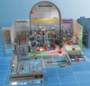
The pre-stressed reinforced concrete shell of the reactor building is clad on its inner side with a steel liner. An annular space at the lower part of the reactor building collects potential leakages from all penetrations. In addition to the primary circuit, the reactor building protects water storage for safety injection and houses the dedicated spreading area for molten core material following a postulated worst-case severe accident.
The reactor building is surrounded by the safeguard and the fuel buildings. The internal structures and components within the reactor, fuel and safeguard buildings (including the plant control room) are protected against external events including aircraft hazard and explosions.
Redundant 100% capacity mechanical and electrical safety systems are strictly separated into three divisions. One additional separated backup division, called Division X, is provided for an essential service water system and a component cooling water system, as well as a fully diverse redundant ultimate heat sink. This Division X provides additional diversification means in case of beyond-design-basis events and can be used for preventive or corrective maintenance on any other train.
Some of the main characteristics of the ATMEA1 design are listed in Table 1.
Economic and environmental benefits have also been extensively factored into the design to maximise the plant performance. The ATMEA1 reactor thus provides:
- A high thermal efficiency up to 37% that leads to fuel economy and reduction of waste production
- A 60-year service life that reduces decommissioning burden for a given level of electricity generation.
- A high availability factor (>92% over the plant life) obtained through fuel cycles of up to two years as well as short refueling outages thanks to design provisions that allow accessibility to the reactor building during operation, space for maintenance, and in-service maintenance thanks to Division X.
- An extended load-follow and frequency control capability that allow the ATMEA1 reactor to be adapted to severe grid requirements—at either 50 or 60 Hz—to provide utilities advanced operational flexibility.
Primary circuit components

The steam generators (SGs) are vertical shell, natural circulation, U-tube heat exchangers with integral moisture separating equipment. They are fitted with an axial economizer to provide increased steam pressure. The axial economizer directs all the feedwater (FW) to the cold leg side of the tube bundle and the largest part of recirculated water to the hot leg, thanks to the double wrapper in the cold leg of the downcomer.
This design enhances the heat exchange efficiency between the primary side and the secondary side and increases the outlet steam pressure compared to a boiler-type SG with the same tube surface. The tube material is alloy 690 TT, which is widely used in SGs throughout the world, and is highly resistant to primary corrosion.
The passive advanced accumulators provide for reactor vessel refill at a high injection flow rate and for core re-flooding at a lower flow rate. As a result, low-head injection pumps, which originally injected the lower flow rate, are no longer necessary, thus simplifying the reactor design. Indeed, in case of rupture or breaches in the primary loops, the loops need to be refilled very quickly. The passive advanced accumulators will thus provide water, first at a high flow rate and then at a lower flow rate, during the first seconds before the safety injection pumps (medium head injection pumps) start. The accumulator is a passive system that is self-activated thanks to hydrostatic pressure difference, and thus requires no electrical triggering systems.
The ATMEA1 core consists of 157 fuel assemblies (FAs) as used in the conventional three-loop cores designed by AREVA and/or MHI. The core also contains a radial heavy neutron reflector designed to improve neutron utilization (thus reducing fuel consumption), to reduce the RPV irradiation. Inspection work is reduced by removing all of the bolts from the high neutron fluence area on this reflector. Each FA consists of fuel rods arranged in a 17x17 square array, together with 24 control rod guide thimbles. The fuel rods contain either slightly-enriched uranium dioxide pellets or MOX pellets. The ATMEA1 reactor can go from a full uranium core to a mix with MOX fuel up to one third of the core for the standard design, and up to 100% without any major design modification. Fuel cycle lengths can be set from 12 to 24 months. The ATMEA1 reactor is capable of operating in load-following mode with a minimum power level of 25%. The reactor can be returned to full power without notice at a rate of 5% per minute.
Safety
The ATMEA1 design is based on safety objectives relative to the most advanced generation of PWRs, including reduced core damage frequency (CDF) of less than 10-5/reactor-year and large release frequency (LRF) of less than 10-6/reactor-year.
The reactor complies with US regulations, US industry consensus codes and standards, ICRP for radioprotection recommendations, International Atomic Energy Agency safety standards [see box], and takes into consideration inputs and requirements from well-established national safety authorities currently engaging with the generation III+ AREVA EPR reactor and MHI APWR, in both national and foreign markets.
The safety design of the ATMEA1 reactor is based primarily on deterministic analyses, and probabilistic analyses. The deterministic approach is based on a strict application of the ‘defence-in-depth’ concept, resulting in:
- Favourable transient plant behaviour thanks to large steam generator inventory and pressurizer steam volume
- Simplification of the safety systems and functional separation
- Mitigation of common-mode failures by segregation and diverse back-up safety functions
- Low sensitivity to failures, including human errors, by incorporation of adequate design margins
- Automation and extended times for operator actions
- Less sensitivity to human errors by optimized digital I&C systems
- Increased robustness of the containment pressure vessel.
The list of design-basis events is based on the US Nuclear Regulatory Commission regulations supplemented by two types of events: those whose probability is high enough to be considered, and those which worldwide operating experience have proven necessary to be incorporated in the design. For all safety analysis, the long-term safe state is retained as safe shutdown state.
Low-probability events with multiple failures and coincident occurrences up to the total loss of safety-grade systems are considered in addition to the deterministic design basis (that is, beyond-design-basis). A probabilistic approach is used to define these events and both a deterministic and probabilistic approach is used to assess the specific measures available for their management.
As a result of all the above considerations on the ATMEA1 design, the probability of severe accidents has been highly reduced, and innovative features practically eliminate energetic scenarios that could lead to early containment failure. In addition, design provisions for a further reduction of the residual risk, core melt mitigation, and the prevention of large releases are implemented.
The ATMEA1 design provides a large autonomy for safety systems and an increased operator response time. In case of loss of outside power, storage capacity of engine fuel for emergency sources are available on-site for at least seven days per power source.
The ATMEA1 reactor integrates top-level safety features to protect, cool and confine the reactor in all situations, including extreme conditions.
Protection
Special care has been taken to protect safety systems in the reactor building and safeguard buildings. The fuel building and emergency power source buildings are protected against a wide range of external hazards, including: seismic events, with a 0.3g safe shutdown earthquake level as a standard design with appropriate design margins; external flooding, with leak-tight buildings housing safety systems as well as equipment; and explosion, missiles, tornadoes, and fire. The ATMEA1 reactor is also designed to take into account the crash of a military or large commercial airplane.
The main requirements to ensure that such an impact will not trigger release of radioactive material exceeding radiological limits are:
1. Structural integrity of the minimal necessary set of buildings housing the important safety functions: containment, the safeguard building, the emergency power sources buildings and the spent fuel pool building
2. Prevention of airplane fuel ingress into the reactor building, safeguard building, fuel building and emergency power source buildings, hence preventing internal fires or explosions
3. Safe shutdown capability
4. Availability on the long-term of emergency core cooling and residual heat removal systems.
Cooling

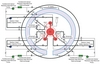
The ATMEA 1 design integrates three independent active safety trains which are protected against external hazards. Each train encompasses mainly:
- The safety injection system (SIS) that injects and re-circulates medium head emergency coolant water to maintain the reactor core’s coolant inventory following a Loss of Coolant Accident (LOCA). Advanced accumulators provide for high flow injection during the first seconds following a large LOCA and then the medium head safety injection pump injects water during subsequent core re-flooding phase
- The containment spray system (CSS) and the residual heat removal system (RHRS). The CSS/RHRS performs normal shutdown cooling, as well as containment spray injection to maintain the reactor building conditions within design limits in the event of a LOCA, for example.
By placing each train in a specific area or division that is separated from the areas or divisions housing the other trains, each safety system train is protected against the propagation of internal hazards (for example, fire, high-energy pipe break, flooding) from one train to any other.
The ATMEA1 reactor also features an in-containment refuelling water storage pit (IRWSP) that is located at the bottom of the containment, under the reactor pit, and feeds the main safety SIS, CSS and RHRS systems. It will also provide for the cooling of the corium in the event of a core melt.
The fuel pool is located outside the reactor building in a dedicated building to simplify access for fuel handling during plant operation and handling of fuel casks. The fuel building is also protected against aircraft hazard and explosions. Fuel pool cooling is ensured by two redundant, safety-related cooling trains, and in case of a beyond-design-basis accident, an additional heat removal system acts as a third redundancy to cool the used fuel pool.
Confinement
As an advanced Generation III+ reactor, the severe accidents mitigation features and systems have been incorporated in the early stages of the reactor design. They aim to achieve the main following safety goals:
- Prevention of high-pressure core melt by high reliability of decay heat removal systems complemented by dedicated primary system overpressure protection
- Discharge of the primary system into the containment in the event of a total loss of secondary side cooling
- Molten core spreading and cooling through a spreading area or core catcher, which is coated with a sacrificial protective material and has a cooling system to protect the basemat
- Prevention of hydrogen detonation by reducing the hydrogen concentration in the containment at an early stage with passive catalytic hydrogen recombiners
- Control of the containment pressure increase by a dedicated Severe Accident Heat Removal System (SAHRS) consisting of a spray system with recirculation through the cooling structure of the melt retention device
- Collection of all potential leaks and prevention of confinement bypass through an annulus.
Author Info:
This article was published in the March 2012 issue of Nuclear Engineering International magazine.
Related ArticlesArgentina pre-qualifies ATMEA1 nuclear plant| Regulatory and post-Fukushima reviews |
| The International Atomic Energy Agency (IAEA) announced completion of a review of ATMEA1 conceptual design safety features in 2008. It found it addressed IAEA’s fundamental safety principles and key design and safety assessment requirements. In February 2011, the Canadian Nuclear Safety Commission announced it had begun a pre-licensing assessment of ATMEA1 for compliance with regulatory requirements, scheduled to be completed in 2013. |