Balance of plant
Super size turbine
29 July 2004The steam turbine for the new nuclear plant in Finland has been designed to have a net output of approximately 1600MWe – a net efficiency of about 37%. What technological advances does it represent and how is the turboset arranged? By Andreas Wichtmann
Finnish electric utility Teollisuuden Voima Oy has signed a contract with the consortium Framatome ANP and Siemens to build an EPR (European Pressurized Water Reactor) at Olkiluoto. The nuclear island of the €3 billion turnkey project will be supplied by Framatome ANP, and the turbine island by Siemens. The new plant is due to start commercial operation in 2009.
The major steam system parameters at steam generator outlet and inlet nozzles are summarised in Table 1.
The turbine generator (see Table 2) is of tandem compound design and consists of a double flow high pressure (HP) turbine and a six-flow low pressure (LP) turbine solidly coupled to a three phase synchronous generator with a directly connected exciter.
TURBOSET
The design of the turboset is based on a detailed design study for the EPR basic design project initiated by Electricité de France (EdF) and started back in 1996. The project aimed to develop a turboset that is capable of achieving the highest power output, with best efficiencies and highest availability.
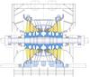
The basis for the development work on the steam turbine was the design of the standardised Konvoi saturated steam turbosets for nuclear power plants and the service and retrofit experience of large nuclear power plant turbosets. A 3D arrangement of the Olkiluoto 3 turboset is shown in Figure 1. The overall length of the shaft train is 68m. Each turbine rotor rests on two bearings.
The steam turbine-generator set is of solid-coupled, tandem compound design comprising one HP and three LP turbine cylinders. Due to the high power output and the relatively high volumetric flow rate, a half speed design is provided. The turbine generator is a four-pole generator inclusive of a brushless exciter set. The condensers are welded rigidly to the outer casings of the LP turbine cylinders and mounted on multi-ball bearings. The LP outer casing features free expansion without causing any change in clearance between internal LP turbine stationary and moving components.
Four combined main steam stop and control valves are arranged below and in front of the HP turbine cylinder. The combined moisture separator reheaters are installed in front of the turbine in an upright position. They each rest on four pendulum supports with axial guidance mounted on foundation beams.
HP turbine
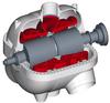
The HP turbine is of double-flow, double shell design with horizontally split outer and inner casings (see Figure 2). An important feature is the double flow design with symmetrically arranged stages and nozzles, which helps prevent significant thrust changes during operation. An optimum number of turbine stages can be installed and small radial clearances between stationary and moving blades ensure a high efficiency of the HP turbine. Due to the relatively low pressure in the outer casing, small flanges are possible. This results in high flexibility during transient operation and short start-up times.
The rotor of the HP turbine consists of a forged, mono-block shaft with forged-on coupling flanges with the moving blades held in slots; the critical speed of the rotor is above the operating speed. The rigid HP rotor has operational advantages over flexible rotors in maintaining the relatively small clearances, no instabilities due to resonance zones during start-up, no power limitation on account of steam turbulence and no self-excited oil film vibration can occur. The blading is of variable reaction type with about 40-50% reaction. All the moving and stationary blades are integrally shrouded and tight fitted together. The integral shrouding has an excellent damping characteristic in service.
The HP turbine operates in the wet steam region. Erosion/corrosion problems are taken care of by appropriate material selection and surface protection. Use is made of steels with chromium contents of about 2% and 13% and chromium steel claddings, which have sufficiently high resistance to erosion/corrosion.
LP turbine
The LP turbine casings are welded structures of horizontally split, double shell design; the LP turbine cylinders are also of the double-flow type (see Figure 3). The exhaust area of the last blade stage comprises 30m2. This will be achieved by an end stage blade with 1830mm profile length. The six-flow configuration reaches a total exhaust area of 180m2.
The rotors of the LP turbine are built-up-type rotors with the moving blades held in slots. The individual rotor segments and coupling flanges are shrink-fitted to the shaft core. Siemens-designed LP-shrunk on disc rotors have a high safety level against stress corrosion cracking gained by design features, material, quality, stress limitation and control of steam purity. Millions of disc service hours have been accumulated without any indication of stress corrosion cracking.
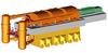
The first flexural critical speed of the LP turbine rotors is below the operating speed. The drum stages are provided with about 50% reaction, and integral shrouded blading is being used. The final stages are standardised, twisted moving blades (see Figure 4). Their degree of reaction differs over the length of the blade in line with the speed of rotation, which also increases sharply over the length of the blade. The last three standardised blades have the advantage of guaranteed vibration frequencies with wide margin between the natural frequency at rated speed and resonance. The moving blades are fixed by means of curved fir-tree roots.
Water droplet impact erosion striking rotor blades at high relative velocities is prevented during all operation modes. The steam path of the LP casing has special design features for water extraction.
EFFICIENCY DESIGN FEATURES
Turbine efficiency is determined primarily by the blading, since this is the component that actually transforms the available energy of the steam into useful work. Research on blade design improvement was started on turbines for fossil steam power application many years ago. The results have been applied to the nuclear steam turbine design for maximum thermodynamical benefit.
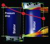
For the drum stages of the HP turbine, Siemens’ latest drum blading technology 3DV (3D variable reaction) will be used (see Figures 5 and 6). This new type of blading eliminates the age-old decision as to what percentage reaction to apply across each row of blades. With 3DV blading, the stage reaction and the stage loading for each row can be numerically optimised to gain higher HP and IP efficiency than was possible with previous blading types.
3DV blading also incorporates the advantages of 3DS-blade technology where reduction of secondary losses in the sidewall area at the hub and tip region is of primary importance. The secondary losses contribute significantly to an efficiency deficit in some HP blades due to the relatively small blade heights.
Due to the low cooling water temperature in Finland the design backpressure is about 25mbar. A large exhaust area of 180m2 gives the optimum exhaust loss reduction and power output gain. It will be achieved by a six-flow LP turbine with an end stage size of 30m2 – a blade of 1830mm profile length. This blade is a fully scaled version of the 8m2 full speed blade, which has 911 years of module service life experience. The mechanical and aerodynamical properties of 8m2 and 30m2 last stage blades are the same.
MATERIAL IMPROVEMENTS
In addition to the flow-related modifications, special attention was given to minimising the risk of stress corrosion cracking of the new low pressure turbine cylinder.
Stress corrosion cracking is likely to occur if the following three factors coincide:
- Steam/condensate impurities (electrical conductivity).
- Material susceptibility to stress corrosion cracking (high yield strength).
- High tensile stresses at the surfaces of the discs (stress concentration).
All of the forged steels used in the low pressure rotors exhibit largely the same behaviour with respect to stress corrosion cracking and crack growth rate. It is therefore impossible to make parts more resistant to stress corrosion cracking merely through choice of materials. Siemens uses a forged steel with a 3.5% nickel and 1.5% chromium content for all its shafts and discs. This steel has excellent through hardenability, even given the large diameters used here. Good fracture toughness and notch toughness can be achieved across the entire cross section with consistently high yield strength.
The third factor which can trigger stress corrosion cracking is the only one which turbine manufacturers can take steps to prevent by ensuring that only compressive stresses or low-magnitude tensile stresses act on the surfaces of the discs.
Siemens uses the finite element method to determine disc stresses caused by centrifugal force and shrink fit. The disc contour and shrink fit are optimised such that the hub area is only subjected to consistently low tensile stresses. Also, nonlinear fracture mechanics analysis will be performed on all highly loaded components to ensure a reliable operation in all hypothetical load cases and worst case assumptions.
In addition to these design measures, special heat and surface treatment processes further increase the resistance of discs to stress corrosion cracking. These are:
- Spraying with water after heat treatment in the steel mill; this causes the hub and outer rim areas to cool faster than the inside of the disc with the result that surface zones of residual compressive stresses occur once the entire component has been properly cooled.
- Shot peening of the hub, web areas and blade grooves of the discs; this eliminates tensile residual stresses resulting from machining operations and produces compressive stresses at the surface.
- Rolling of all shaft radii, axial keyways and LP blade root radii with highest stress.
For the anti-rotation bolts, a method which has been used successfully for many years is to provide the keyways with a circumferential stress-relief groove outside the shrink fit area. After reaming and honing, the keyways are rolled with a special tool and honed a second time. This process produces such high compressive stresses at the surface of the keyways that tensile stresses cannot possibly occur in the low pressure rotors, even in operation.
Author Info:
Andreas Wichtmann, Siemens AG, Power Generation, Rheinstrasse 100, 45478 Mülheim an der Ruhr, Germany
TablesTable 1: Steam system parameters Table 2: Turbine generator data