Transport
Simplifying thermal creep
4 March 2011TN International (TNI) recently started a study of irradiated fuel cladding thermal creep in routine transport conditions to evaluate creep rupture risk of LWR fuel. Analytical calculations are not possible because of creep behaviour non-linearity and large number of input parameters. Finite Elements Analysis (FEA) is very time-consuming and inflexible in practice. Therefore, TN International has developed a simplified FORTRAN calculation model currently undergoing validation. By Maurice Dallongeville, Cédric Langlade and Aravinda Zéachandirin
Fuel cladding thermal creep consists of progressive local swelling of cladding parts submitted to high temperature and internal pressure of filling and fission gas. This swelling produces a decrease of the cladding thickness because of its circumferential stretching and potentially leads to a rupture, with gas and fissile material release.
Analytical calculations are not possible because of creep behaviour non-linearity and the large number of input parameters. In the early stages, TNI studied fuel cladding creep using finite element analysis (FEA). This method was very time and cost-consuming, and not flexible in practice as it requires additional programming. Therefore, TNI has developed a simplified FORTRAN calculation model, which is described here.
Physical phenomena
In typical transport conditions, maximum fuel cladding temperature is reached at the centre of the fuel assembly located in one of the central positions of the cask basket. Indeed, basket wall temperatures are higher for central positions than for peripheral positions. The hottest fuel cladding can reach temperatures between 400 and 500 °C in transport conditions.
Creep rate is influenced by a combination of several parameters: temperature profile and evolution, stress level (from internal gas pressure), irradiation and oxidation profiles. In particular, the combination of the axial thermal profile (maximum value and sharpness of the peak zone) and of the axial irradiation profile have a significant influence on the maximum radial cladding deformation in relation to time obtained, and to its axial location. A cladding rupture occurs when a critical strain is reached locally.
The calculation of the cladding deformation focuses on the hottest fuel pin during transport, and the verification of cladding integrity on the concerned temperature and stress domains. It requires knowledge of a creep law and a non-rupture criterion (based on a material rupture limit) that guarantees the cladding mechanical creep strength. Both need to be validated for the material.
The main parameters to consider as calculation hypotheses for an irradiated cladding thermal creep study are presented here for a used PWR fuel pin.
- Geometry: The geometry of a complete fuel pin is considered at 20 °C and 1 bar pressure.
- Mechanical characteristics: Thermal and mechanical properties of Zircaloy cladding and fuel pellets are used. Fuel pellets are not explicitly modelled but they are taken into account in the free volume calculation. The various possible zirconium-based cladding materials with associated composition, cold working and heat treatment, and consequently different in-reactor damage, lead to different thermal creep laws (and sometimes rupture criteria) that require separate treatment.
- Displacement conditions: The considered model is axis-symmetrical, and the nodes situated on the revolution axis of cladding tube have nil radial displacements due to their axis-symmetry. One node of the lower plug is fixed.
- Temperature profiles: Temperature axial profiles representative of four-cycle irradiated fuel are imposed along the cladding, whose transverse sections are homogeneous in temperature during transport. These temperature profiles are crenels that are smoothed at their angles to simulate axial thermal conduction effects and to avoid creation of unrealistic local mechanical stresses. Evolution of the temperature profiles for a given initial maximum cladding temperature is considered at 0, 4, 8 and 12 months, and permits the description of fuel cooling in the cask. A linear interpolation of these temperature profiles is carried out for times in between.
- Fluence profile: Axial fluence profiles allow initialisation of the creep law irradiation variable in the model.
- Corrosion profile: The consideration of the axial profiles of the cladding’s maximum outer corrosion allows the initialisation of resistant cladding thickness in the model. The development of outer cladding oxidation during transport or storage is not considered because it is supposed that fuel assemblies are loaded into the cask in a neutral atmosphere.
- Internal pressure at 20 °C: Gas pressure imposed on the inner side of the cladding tube and initialised at the standard absolute value of 20 °C or at higher value depending on the calculation case. (A study of the initial pressure influence uses higher values.) The pressure field stays perpendicular to the deformed mesh during time. Absolute pressure is computed by the ideal gas equation at each calculation step, taking into account the absolute temperatures and the associated local free volumes computed by the ideal gas equation. The gas mole number is considered constant and no additional gas release is taken into account in the calculation of the thermodynamic balance.
Thermal creep laws
The thermal creep laws of irradiated Zircaloy claddings describe the deformation velocity ?* (sigma)*, T, (psi), e*) in relation to:
- loadings at time t:
-stresses via the equivalent tensile (Von Mises) stress (sigma)*
-absolute temperature T
- two internal variables reflecting the material history:
- the plastic equivalent deformation e*, which reflects the isotropic cold-work hardening linked to the deformation;
- the variable (psi), which reflects the irradiation hardening linked to the density of irradiation defects.
The general form of the (secondary) creep term of the law is similar to the ones mentioned in [1], [2] and [3].
At the beginning, the equivalent deformation e* is nil and the irradiation hardening variable (psi) is equal to the final cladding in-reactor irradiation fluence profile (phi)t (z), where z is the axial position, or a corresponding constant.
Creep rupture criterion
The limit elongation of irradiated Zircaloy claddings is generally established in relation to stress and irradiation variables:

e*and (sigma)* are the same as in the creep law, (sigma)c is a threshold stress depending on the temperature and on the irradiation hardening, and a and b are coefficients from the correlation of creep data.
This criterion is a generalization of a similar formulation [3] for high-tin Zircaloy 4 in which F(?) = (phi)t. The coefficients of limit equivalent deformation for high-tin Zircaloy 4 are also given in [3]. It should normally be used with circumferential stress and strain but, in fact, using equivalent values is simpler and is slightly more conservative.
The criterion used in creep calculations enables the determination of the duration until cladding creep rupture. However, even in cases of cladding rupture, the calculations are generally carried out for one year to obtain the theoretical maximum elongation in this period.
The limit equivalent deformation is calculated from the criterion formula and from the cladding stresses and irradiation variables obtained by the mechanical calculation. It is compared to the cumulated creep deformation at each time-step for all integration points along the cladding. The corresponding differences are margins that should stay negative to avoid a cladding rupture risk.
The non-rupture criterion can be checked for local parameters, or more conservatively, for semi-local parameters (the whole cladding envelope), or even more conservatively, for global values (the whole cladding and plug envelope).
Fortran model
Thermal creep calculations by FEA are usually carried out with a finite element code completed through additional programming of data, laws and criteria generally written in code-specific and/or FORTRAN language. Because of the non-linearity of creep laws, FEAs are time-consuming and costly.
The necessity to have a simpler model to check FEA results, and also, to produce results on other cases with similar configurations has led TNI to explore the possibility of a simplified calculation program, which would nevertheless include many interactions between the various parameters’ effects.
Therefore, TNI is currently developing a simplified creep model with similar functional calculation capacity to FEA codes, and including the symmetrical-axis mechanical calculation of cladding thermal creep and the associated additional programming. This calculation model is aimed to be quicker than FEA codes and to have good precision.
Calculation principles
The modelling takes into account the main phenomena, parameters, and their interaction. It has exactly the same input parameter values and level of precision as the FEA model. The main calculation principles applied to develop this simplified model are:
- Preliminary filtering of the initialisation profiles: The input profiles are given by linear segments and their associated axial positions are used to produce the minimum effective meshing generation. A preliminary simplification step eliminates unnecessary intermediate points and manages very close points (points are merged if distance is less than a minimum gap).
- Meshing generation: In addition to nodes selected based on geometry, and based on various (filtered) profiles, intermediate nodes are also created on the basis of a maximum mesh element length. Axial mesh refinement is chosen to give good description of temperature and irradiation axial profiles. Cladding mesh has one element in thickness in order to remain simple and to calculate average stress.
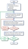
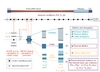
- Overall calculation on a whole fuel pin (Figure 1): Parallel calculations allow the determination of creep deformations at cladding nodes and of the volumes in deformed geometry, and then the updating of internal pressure by integration of the gas state equation for a constant number of gas moles (as in the additional coding in FEA). The local free volumes are calculated by subtracting the expanded cladding internal volume and fuel pellets’ external volume on each mesh, and they are updated at all iterations.
- Iterative resolution: The numerical scheme used (an iterative, parabolic, time-integration method for functions of several parameters) creates a very good consistency with the time evolution of the various calculated parameters and with the use of a variable time-step. The variable time-step produces a significant improvement of the calculation velocity as soon as the increase is at least few percentage points from one time-step to the next. All interrelated functions are developed versus time; this method is simpler to calculate and consistent. The simultaneous convergence process with integration of the parabolic time derivatives of functions ensures a very good representation of the mutual interactions of functions and of their actual time evolutions. Moderate time-step variations (below about 10 %) permit a good precision of the numerical scheme.
- Recommended maximum time-step: A recommended maximum time-step selected at all calculated times upon all calculated nodes is the minimum value of several types of calculated time-steps. The maximum time-step necessary to avoid calculation divergence in the irradiation variable equation is reduced with security margins and then compared to a maximum time-step necessary to keep a good precision of the numerical scheme. The resulting time-step is finally compared to an experience feedback time-step. This latter logically proposes a low initial value followed by an exponential evolution until an asymptotic limiting value. The recommended maximum envelope time-step finally retained guarantees a significant margin for the known divergence risks and it incorporates optimisation knowledge.
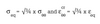
- Algorithms and equations: The general algorithm of the simplified program (Figure 2) shows the iterative solving of the main equations at each time-step and details the elementary initialisations and calculations used. The physical parameters concerned are the un-corroded cladding thickness and outer diameter, and the fuel pin relative internal pressure. The cladding stresses inducing thermal creep are developed from hydrostatic and deviator stresses. The stress/strain equations consider the incompressibility-deformation relationship and the Sodenberg creep deformation relationships during a time-step. Associated to some further simplifications of formula, this system of equations leads to a simplified model for creep resolution:
- Relationship during time-step:
- Ratios of equivalent to circumferential values:


Use of equivalent stresses for the rupture criterion
The rupture criterion [1] must be applied in principle with the average effective cladding circumferential deformation and average stress ((sigma)eff = (sigma)(theta theta) - (sigma)rr). However, corresponding equivalent Von Mises stress and strain were used instead, as they are easier to obtain and give consistent results with the previous criterion.
Software characteristics
The thermal creep program is written in FORTRAN 77. The organisation of the software, which includes sub-programs, and the use of general formulas for creep laws and implementation of rupture criteria, enables users to switch easily from one cladding material to another.
The main electronics files generated in use relate to the data, calculation listing, mesh, initial conditions and calculation results. The calculation results are analysed extensively in spreadsheet graphs (more severe criteria curves in relation to time, axial profiles at several times, time curves at several axial positions). Results comparisons are also available on spreadsheet graphs (more severe curves in relation to time or axial profiles at several times) between a case calculated by this program and another case (same program and different hypotheses, or same hypotheses and calculation by FEA).
Typical calculation duration for a given case is a few seconds for the calculation, about five times more to write the output files, and a few minutes for results to transfer into spreadsheet graphs and for their further visual examination. By comparison, FEA calculations of similar cases take from several hours to a few days, and export of data into spreadsheets is not optimised and currently takes a few hours.
The FORTRAN program can be applied to all thermal creep calculations in a closed cask (whose applications range from routine transport lasting from a week to a year, vacuum drying, a theoretical half-hour fire for regulatory purposes, accidental partial emptying of storage pool over a few hours, and interim storage) provided that adequate creep laws and rupture criteria are available.
It will also enable studies necessary to support safety demonstrations, either with a simplified envelope approach expressed in maximum fuel pin temperature for several fuel pin types, or a direct approach realised by complete creep calculations carried out for each case.
The program qualification plan, currently under development, consists of:
- Functionality tests concerning input and output data
- FORTRAN program checks on the physical equations and numerical scheme aspects
- Comparisons with available FEA calculations
- Several analyses of differential modification tests of the FORTRAN program models
- Sensitivity studies on all involved physical parameters, in particular to investigate the potential need to model them, whether their level of simplification in the model show the interest or not to model them, and whether their level of simplification in the model is acceptable.
Application example
A preliminary comparison was carried out with the simplified program developed by TNI and with the FEA code CAST3M [4] for a fuel pin from a 17x17 assembly in a 900 MWe PWR reactor. A case with initial maximum temperature of 450°C is studied here. The associated temperature axial profile is presented in Figure 3. The cladding material is high-tin Zircaloy-4 (Zr4). The cladding irradiation fluence corresponds to a four-cycle in-reactor irradiation.
The outer thickness of corroded cladding is not differentiated from sound metal, in accordance with the creep law development. The standard internal absolute pressure used is 62 MPa. FEA calculations use initial time-step variation in high stages over the first 30 hours, while the FORTRAN program time-steps increase regularly.
The creep laws and criteria used have been developed by CEA R&D laboratories. Thermal creep behaviour used for high-tin Zr4 material includes irradiation defect recoveries with temperature, but does not include cold-work hardening recovery. The thermal creep behaviour was established from tests on four-cycle-irradiated cladding with temperature conditions from 450°C to 600°C and with a stress domain from about 30 MPa to 130 MPa.
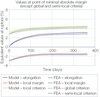
Creep margins-to-rupture are established with local deformations and rupture criterion values for the simplified model and presented on curves versus time for points with minimum local margin. Local, semi-local and global margins-to-rupture are established for FEA creep calculations and give similar results with the corresponding gradation of conservatism.
The rupture parameters of the FEA curves presented versus time are the maximum cladding deformation, the semi-local and global rupture criterion, and the minimum local margin (established from FEA local deformation and criterion not shown here).
Results
Principal results of this 450 °C case are shown for both models in the following figures:
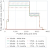
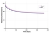
- Internal pressure profile in relation to time (Figure 4) and equivalent stresses axial profile at several times (Figure 5)
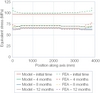
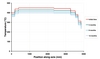
- Maximum cumulated equivalent deformation axial profile at several times (Figure 6) and deformation/criterion/ margin-to-rupture in relation to time (Figure 7)
There is no rupture risk for a one-year transport (typical transport duration is about a week) and the minimum deformation margin against rupture is still 1.66% at end of the year.
Comparison with FEA calculations
Discrepancies in the amount of creep resulting from the FEA calculation and the FORTRAN model are small and show that the TNI model enables carrying out low-cost studies with good accuracy. Furthermore, this program can still be optimised further, as it is not yet fully validated.
The values determined by the TNI program are mainly average values within cladding thickness, while FEA results are maximum values within cladding thickness, which are then potentially situated on other radial positions. However, for comparison purposes, the TNI program can also show stresses and irradiation variables in post-treatment estimations of inner and outer cladding radius.
Creep calculation with the FEA code CAST3M involves the basic mechanical program and additional programming in FORTRAN and specific CAST3M language that define input data, specific equations for irradiation variable and thermodynamic balance for internal pressure calculation, as well as instructions for presentation of results. FEA calculations and output analysis take a long time, leading to particularly prohibitive costs and deadlines.
The calculation model of the FORTRAN program integrates all the system equations in an optimal way and uses an efficient numerical scheme. Data are in an external input file read by the FORTRAN program when running. The overall program is particularly simple to understand and check, so it can easily be corrected and developed. It runs quickly and its output analysis chain, linked to spreadsheets, is efficient.
Consequently, the simplified model is more adapted to daily use than FEA, which is more pertinent for indirect validation of the FORTRAN program (when there is no convenient test result) or for independent comparative calculations that may be required in some projects.
Conclusion and perspective
Currently, the FORTRAN modelling gives good results because, although simplified, it nevertheless takes into account the main thermal creep phenomena, parameters, and their interactions. The principle used for modelling is very efficient and the actual program, which still has a significant margin of progression, is open to further updates and developments (such as introduction of the dynamic outer cladding oxidation during the transport, or a secondary plenum in the bottom part of fuel pins).
The FORTRAN simplified program is now under validation and will allow reliable evaluations of LWR fuel pin rupture risk by thermal creep, with large time and means benefits. It uses generic thermal creep laws and can be applied to closed cask routine transport lasting from a week to a year, vacuum drying, half-hour fire and interim storage with appropriate creep laws and rupture criteria.
Author Info:
Maurice Dallongeville, Cédric Langlade and Aravinda Zéachandirin, TN International (Areva), 1 rue des hérons, 78180 Montigny-le-Bretonneux, France
| References |
| [1] C. Cappelaere, R. Limon, et al, “Long term behavior of the spent fuel cladding in dry storage conditions,†Radioactive Waste Management and Environmental Remediation— ASME 2001, October 2001 |