DECOMMISSIONING / ROBOTICS
A hostile workplace
21 December 2004Maintenance and decommissioning tasks are frequently carried out in areas where human access is either very limited or completely prohibited. By Wilhelm Bazlen
Wherever handling of material is required in areas that cannot be accessed by people, due to risks such as explosion or radiation, then machines have to be used.
In situations where the procedures to be carried out are frequently repeated a robot or a dedicated device may be used. The amount of effort required to design a device or programme a robot has to be taken into consideration. Where there is less repetition or even individual handling of each ‘work piece’, the working area remains constant and is not too large (for example, on a workbench) through-wall manipulators can be used. This solution is limited to the force that can be physically applied by the operator. In cases where these solutions would be inadequate a hydraulic or electrically powered manipulator could be used.

EMSM3 single arm, mobile system
However, if tactile working is required then the application of master-slave manipulators (MSMs) with force feedback should be taken into consideration. Tactile working is required when sensitivity is necessary to control the applied force rate and to be aware of any resistance such as when handling material or items in three dimensions or when using tools. A combination of tactile working and a high payload can be achieved by means of a force feedback with adjustable rates below 100%, which means that only a proportion of the forces available to the slave (working) arm are applied to the master (control) arm. The forces available at the working arm are therefore not limited to the strength of the operator and that the physical stress on the operator is greatly reduced.

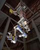
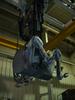
Crane transported EMSM3 double arm system
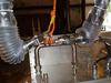
As the slave arm is electrically driven, this ‘working arm’ can be located at a remote distance from the control equipment (cubicle) – up to several hundred metres is possible. The main design challenge for working in a radiation environment is to exclude any electronics from the slave arm and house them all in the control cubicle. The complexity of this design requirement can be seen in that there are phase currents for up to 16 motors, chopped from a 325VDC circuit. The resolver signals, located directly adjacent to the motors, are analogue signals that are finally converted to 14-bit position information. It is not possible to amplify the signals at the sensor output due to space limitations and the potential presence of radiation, which would be detrimental to the amplifiers.
The main components are connected by cables, making the system very mobile and allowing the slave to be used as a highly sophisticated device at the end of mobile or built-in cranes, articulated booms or other specialist access delivery systems. Normally the application of each manipulator system is different and the management of the cables (for example, two cables of approximately 18mm diameter are required for eight joints) is customised to suit.

EMSM3 single arm, intrinsically sealed
HARCH CONDITIONS
As the manipulators are normally used in areas where people have to be excluded, it is necessary to consider all of the effects that will arise as a result of the adverse or harsh environmental and radiological conditions. Considerable customisation had to be undertaken when Telerob supplied MSMs for applications in environments with nitric acid vapour or mercury vapour atmosphere combined with a radiological tolerance of 1MGy. It was necessary to consider each material that was to be used in the design in detail. Each shell material had to be checked for chemical resistance and all of the shell components for contamination traps. The whole design had to be checked and modified where necessary to protect the internal reliability of the slave arm against the ingress of airborne or condensing contamination. It was necessary to prevent this type of contamination creeping into the internal structure as it could not then be easily decontaminated.

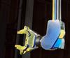
EMSM2b double arm system, booted
Environmental resistance
The stringent design procedures that ensure the shells of the manipulators are chemically resistant allow more flexibility in the remaining structure of the system. As the EMSM3 (maximum payload of 100kg at a 2800mm reach) is an intrinsically closed system, only the shell materials (metal housings and seals) have to be resistant. This is largely achieved by designing the metal housing parts in stainless steel. To reduce the risk of ingress of contamination to a minimum, rotating seals with double lips or two individual seals were designed into each potential leakage path. All threaded fixings were tapped into blind holes so that no through holes were introduced and the corresponding screw heads were combined with a seal washer.
As the EMSM2b system (maximum payload of 45kg at a 1550mm reach) has an open structure, a housing is necessary around the fixed parts of the manipulator arm and the arm itself is equipped with a sleeve or boot. The gripper, standing out of the sleeve and the housing around the fixed part is made of stainless steel. To avoid ingress through functional gaps and potentially damaged sleeves and housings the booting is raised to a slightly positive pressure to ensure that gas flows from inside to outside.
Radiological resistance
Any material used in the whole working arm had to be checked specially for its radiation tolerance. The customer confirmed that the assumption that high temperature resistance also means high radiation tolerance was not a sufficient selection criterion. (The most popular example for this being polytetrafluoroethylene, or PTFE, which actually has a rather low radiation resistance). A good deal of research therefore had to be carried out to investigate which materials could be used for connector bodies, limit switches, cable ties, cable insulations, sealing materials and so on.

Crane transported EMSM2b double arm system
The biggest challenge was probably that placed on the manufacturer of the servo motors to select suitable materials for these units and to provide a list containing each individual material inside the motor down to the material for bandaging the winding overhangs or the varnish on the windings in subassemblies such as the brakes and so on. As there was no suitable resolver commercially available that was capable of
withstanding 1MGy (with appropriate certification), one had to be specially designed. For the set of relays, which are inside the motors to switch between the resolver and the absolute encoder, no radiological data could be provided by the distributor. Therefore a number of relays were irradiated up to 250kGy and it was found that they could survive this dose level without failures. As the relays are only necessary as a start up aid and the system can also be started manually, it was agreed with the customer that this tolerance is sufficient and the relays were to be considered as consumable items to be replaced after 200kGy. The relays are placed on a relay board inside the motor junction box, the boards are fully equipped with connectors and held down by springs. No open wire ends and no small items (such as nuts and washers) are to be handled inside the junction box when changing the relay boards.

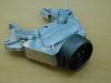
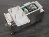
Motor/gear unit, containing all the necessary electrical components for a whole joint quick release relay board behind a removable lid
The system contains three types of grease: one for the gears (high resistance to mechanical pressure); another one for the bearings (highly flexible); and a third one as an assembly aid for the seals (not affecting plastics). These greases had to be verified and partly replaced by others. Verification of the greases for radiation tolerance and also tolerance to each other was necessary as it was acknowledged that some mixing of them could not be avoided over the long term. There was no electronically based problem in getting the arms prepared to the required radiation tolerance as they were originally designed for use in such an environment and therefore do not contain any electronic components (no semiconductors) at all. As standard electronics withstand less than a hundred Gray, the original design had already located these inside the control cubicle with only electromechanical components located in the working arms. Effort had to be undertaken to ensure smooth running of the controls and drives at distances of up to 300m.
Manipulator maintenance
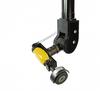
The grippers of all systems can be removed from the arm remotely or by means of a few operations. This is beneficial because the gripper is the main part of each manipulator that comes into contact with any hazardous material and so is usually the most contaminated component. There are also contamination traps caused by the structure of the many moving parts of the gripper that cannot be housed or booted because of the need to maintain functionality. An additional advantage in being able to easily remove the gripper is the possibility to fit other customised equipment (for example, tools and specialist devices) onto the remaining wrist stud.
To ensure that the manipulator arms are as easy as possible to maintain, all electrical components are located inside the motor/gear units (motor, brake, position sensor and so on). The units are simply fixed by two or four screws and the shaft has a locating spline. After releasing the screws the units can be unplugged and replaced by a spare one. Driving the arm to the set-up position and setting up the position sensors is carried out later from the operator panel. This sequence minimises the number of persons and the time spent in the hazardous area.

Undocked gripper
There is normally one type of motor/gear unit in the whole arm. This helps to reduce the amount of material to be brought in and out of the restricted area. This also allows motors to be swapped from one joint to another to assist in troubleshooting and fault finding.
KARLSRUHE REPROCESSING PLANT
The Wiederaufarbeitungsanlage Karlsruhe (Karlsruhe Reprocessing Plant, WAK) was constructed as a prototype plant under the project management of the Forschungszentrum Karlsruhe (Karlsruhe Research Centre). The original objective was to gather experience with regard to the construction of an industrial-scale reprocessing plant. For this purpose, an operation company, namely, the Wiederaufarbeitungsanlage Karlsruhe Betriebsgesellschaft mbH was founded.

Docked gripper
In 1971, WAK started operation as a test facility in order to gather experience in reprocessing technology and to test new developments. These tasks were found to be of particular significance to the construction and operation of a future industrial-scale reprocessing plant. When the plan to construct a large-scale reprocessing plant at Wackersdorf was given up at the end of 1990, however, the reprocessing operation of the Karlsruhe plant was terminated.
Once the decision to terminate the reprocessing operation was made, the responsible institutions decided to decommission and completely dismantle the whole plant giving rise to the following activities:
Remaining operation
- Maintaining safe operation of those plant sections that are not shutdown upon the termination of the reprocessing operation.
- Operation of storage facilities for the high-level liquid wastes arising from reprocessing.
Dismantling
- Decommissioning and dismantling of the facilities in the buildings that are largely restricted or controlled areas. This part of the WAK activities is covered below.
- Demolition of the buildings and subsequent re-cultivation of the premises.
Waste management
- Operation of the plant for the vitrification of the high-level liquid wastes arising from reprocessing.

Docked grinder
A Telerob EMSM3 dual arm system was selected for the tasks as this is a powerful MSM that has a maximum payload of 100kg at a 2800mm reach with force feedback rate selections of 1:10, 1:20 and 1:50. Using the appropriate feedback rate, the operator is able to do rough work such as loading scrap into a container or fine work when handling tools such as disc cutters or impact wrenches. For management of loads that were too heavy for the manipulator it was possible to use a chain hoist that was also fixed to the manipulator carrying system.
The manipulator operators performed the slinging activities and hooked the slings onto the hoist following the normal procedure for material handling of heavy loads. When the use of tools was necessary, they were gripped from a tool rack located above the base of the manipulator. As the movement of each manipulator segment is only limited by its adjacent segment, most joints have a moving area of nearly 360º, which made it easy to grip the tools from the tool rack.
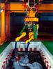
In one section of the plant being dismantled the manipulator carrying system consisted of a rail mounted gantry crane, equipped with a rotation unit under its lower block, which allowed the manipulator arms to turn in the necessary directions. The overall distance between the control centre and the arms, routed through buildings, via the crane, hoist, and rotation unit resulted in a cable length of approximately 150m. However, during the project design phase the design and trials for a cable length of 300m were made, as the final cable routing and length were not known at that time.
Another part of WAK to be dismantled only allowed side access and, as a large number of handling tasks had to be undertaken, again a Telerob EMSM3 manipulator was selected. In this case the manipulator’s working arm is fixed to remote controlled track driven system with an articulated boom, similar to an excavator. The other tools to be used for dismantling such as scrab shears, big nibblers or other devices are also deployed by means of the boom into their working position. The EMSM3 arm and the other tools are equipped with an adaptor plate which mates with an adaptor plate at the boom’s front end. This enables changing the tools and the manipulator arm to be carried out completely remotely. The tools and manipulator are located in suitable cradles when not in use.
Author Info:
Wilhelm Bazlen, telerob GmbH, Vogelsangstrasse 8, 73760 Ostfildern, Germany